|
|
Because of the ending of the Central Jersey S Scalers Get
Togethers and I have my home layout running now, in February 2013 I decided to
sell my beloved 8 track wide S-Mod yard I started building in 1989 as
described below. It was a tough decision but it had not been used in 4
years. It was too much rework to somehow use it with my new home layout I was
building. For the first time since 1989 I have NO S-Mod modules. I still like and believe in S-Mod. With the ending of the CJSS Get
Togethers I will not be building more though.
The hosting clubs for the NASG Conventions get layouts set up from
regional members. I am sure I would not be driving 1000+ miles with S-Mod
sections to set up a layout at a convention. The History Of S Scale Modules S Scale to go! Don DeWitt was very active as the NASG S-Mod module coordinator
in the late 1980s to the early 1990s. He was instrumental in forming
the S-Mod Standards. The current NASG S-Mod page here. When I first got into S Scale most of the running I did was on
S Scale Modules because there were no permanent S layouts in my area. I
initially went to the Central Jersey S Scalers meetings – now inactive. Their
annual Fall Get Together is where I discovered S Scale in the first place in
1987. I really looked forward to those early meets because it was the only place for a whole year I could
run my then new to me S Scale trains. |
|


In the late 1980s I co-founded the South Jersey S Scalers with
the intention of stirring interest in S Scale in the South Jersey area and
making our own S Scale modular layout. I started my own 2’ x 20’ long double
ended yard module with the idea that you could be at a public show and bring
one train in for a rest while sending another one out without a break in the
action. The module interest never blossomed. The South Jersey S Scalers became
the South Jersey S Gaugers. They built their own Sectional Hi Rail
portable layout, and are in the process of building another much larger Hi Rail
portable layout.
Much of the below information is a
little outdated. The S-Mod electrical standards are in a slow process of being updated for DCC.
These modules were built well before DCC and were designed for Cab Control. But
the construction ideas are the same for the modules and legs etc.
Design Considerations
Setting up a layout was a careful time consuming process that
included the loadout, the bolting on of many loose legs and the hours of
fitting many loose bridge rails that were supposed to all be exactly 4” long
but never were. The module tear down on a cold drizzly October Sunday at 4:00
at the Jersey City NJ Communipaw Train Show got downright ugly. Everyone wanted to get home.
Luckily no major damage happened but there were some accidents and
bruised modules. After spending a few years helping CJSS set up and tear down
their modules, I knew that my own modules would have to be designed better.
Bill’s rules for designing better S Scale modules
Rule 1. Life is too short to put on and take legs off of modules.
Rule 2. It MUST be easy to
transport, set up and break down.
Rule 3. Avoid using the 4” loose bridge rails wherever possible. Other
scales sectional track like Atlas Snap Track and use a straight section for
this instead of loose 4“ rails. S still does not have a straight section
comparable to Snap Track. Only use the bridge rails
where the modules interface with another “unknown” module. Captive module
sections should use bridge rail sections as you will see below in Design
Features item 2 and on S Scale Modules page 2.
Rule 4. All equipment must be able to run on it. All turnouts are on my
yard module are #6 except the crossovers which are #8.
Pine = BAD Cabinet Grade Birch
Plywood = GOOD
I cannot say enough about using cabinet grade plywood. I have
been around wood all my life. My father took his apprenticeship and was
essentially a professional woodworker (Industrial Patternmaker) for much of his
life. He has woodworking tools that most would not know how to use. I simply
will NOT make a module frame or benchwork from pine or similar. I have seen it
do too many bad things over time. My frames for my original yard are getting on
20 years old now. They have not moved at all.
Back when the South Jersey S Gaugers started their first layout
they bought pine frames from a club member that was a wood shop teacher. They
were about 3/4 x 2 1/2, had dovetail joints, were screwed glued and tattooed
made from the clearest pine you would find. The frames were extremely light. I
was the only one with ANY module experience. I was the only one that said don’t
buy them. Of course they did not listen - why should they, I don’t know what I
am talking about. I washed my hands of the whole thing. About a year later I
was invited to see their progress which was extensive. There was track down
with some scenery started. The first thing I noticed was the custom bent STEEL
angles that were heavily bolted to all the sides of the "lightweight"
frames. No one even acknowledged that I "might" have been right.
By the time you cut a sheet of plywood into 3” wide strips, the
yield is great. If you contract with a
cabinet making shop that has a panel saw, chances are you can buy the wood
perfectly cut right from them in ready to use strips. There is no sawdust (from
that) to contend with.
Again, I simply will NOT use pine (or similar) for benchwork or
module frames
The NASG S-Mod standards are very flexible with track
placement in comparison to other standards such as N-Trak.
The 4 big standards are:
Rule 1. You must have 2 ¾” track centers on
double track mainlines.
Rule 2.
You must have 42” from the floor to the top of the railhead with ½” + -
adjustment bolts on the bottom of your legs.
Rule 3. You must have a 2” section of roadbed
without rails at the ends where your modules connect to other’s modules. You
can do whatever you want if your module will always connect to another one of
your modules.
Rule 4. You must have modules that are
multiples of 4’ long total.
(Ex. You cannot come to a meet with 18’ of
modules, but 16’ or 20’ is good)
Note – S Free Mo does not subscribe to the making of modules in
increments of 4’ in length rule. I do not practice the S Free Mo philosophy.
Note 2
The S-Mod Gurus have strongly suggested that I add this disclaimer….
"If you are going to want your module to be used in a loop
layout, then you probably need to make your module a multiple of 4 ft in
length. Anything other than a multiple
of 4 ft, may need a spacer module which may or may not
be available. If you bring your own spacer module to place at the end of your
module, or elsewhere on the opposite side of the loop, then there should be
less of a problem.
If you do not build a module that is a multiple of 4 ft, then you
may not be allowed in a loop layout with your module. You could be added to a branchline, IF the
branchline exists in the proposed layout.
If you NEVER want to be in a loop, then the length of your module
does not matter, except in the case where space is limited for the
layout."
That is it! It is very
flexible it you asked me.
Recent on line conversations promoting S “Free
Mo” modules get completely lost on me as we
already have a flexible established module standard. What more could you
possibly want or what part of S-Mod is too restricting? Most of the other S-Mod
standards have to do with the wiring for multiple cabs that are really not
necessary now since we are now mostly using DCC. If I were to make a new module
today I would wire it for DCC only.
I thought that I would hand lay all the track because at that
time the flex track available was on the delicate side. If you snagged a rail
in transit, it could be ripped off without a chance of it ever being repaired.
I had a Kadee Spiker at the time. I will never hand lay track again! I estimate that
I glued 5000+ ties down by hand one at a time.
Here is the track plan for my yard.
Public viewing area
6’ section 4’
section 4’ section 6’ section
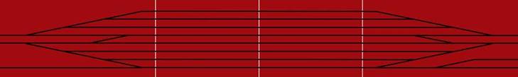
Control Panel
If I could do it again, I would only make it 6 tracks wide. 8 tracks
are too much in 2’ wide. The outside tracks are very close to the edge. Luckily
no accidents have happened because of this.
Design Features
1. I went to great to great lengths to design legs that not
removable and fold up under the modules. I custom made bolts with wing nuts
welded on the heads so a wrench is not needed to put the bolts in. The bolts
run through custom made ¼” pipe bushings so the bolts never wear the wood. One
bolt is set permanently in place with a stop nut as the pivot. The other bolt
has the wing nut on it for a head. These bolts are then inserted through the
legs to lock them in place for storage. 3 of the 4 sections have 4 legs. The
one 4’ section only has 2 legs.
2. Somewhat as an afterthought, I thought of how to connect the
tracks without using 24) 4” long bridge rails. I routed the plywood deck down
about 1/32” x 1 1/2” wide. I then cut 3 aluminum strips 3” x 24” that I mounted
3” long custom made wood roadbed sections that matched the Homabed profile.
Next I mounted rails that are 4” long so they stick out ½” on each side to join
the modules roadbed. All you need is a small straight blade screwdriver and
sometimes needle nose pliers to slide the rail joiners out. When setting the
modules up all I do is set the bridge rail section in place, slide the rail
joiners out and I am done. There are NO loose 4” bridge rails!
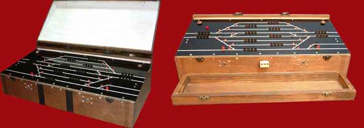
3. The control panel folds up into a suitcase. I wanted it to be
self sustaining because there was always the fear that someone would forget to
bring a transformer to power the layout for a show. Even from the beginning the
control panel housed a powerful transformer. It has 12 “break before make” 4
button push button cab block switches. As you push a button to change from one
cab to another it disengages the current block before engaging the new black
stopping any shorts of cross cab interference. They also fit the S-Mod standard
of having 2 main and 2 local cabs. They
are kind of like the push buttons on the radios in 1960s cars. I don’t remember
who made them or where I got them now. I may have bought them here http://www.allelectronics.com as I found an old credit card bill from when I was buying electrical
supplies for it. They were a bit pricey at about $25.00 each. Now that we are
running DCC, we just put all the cabs to red. I also put my NCE
DCC Power Booster in there
as well. The control panel bolts onto the main 4’ control section. There is a
diagonal brace that bolts on and supports that panel without needing an
additional leg.
4. I thought that I could make the module so that you could use
12 feet, or 16 feet of if you did not have room for all 20 feet. It is not
possible to run 8 tracks perfectly parallel for that distance, so I now a have
a single module that is 20’ long.
5. ALL of the turnouts are powered! This comes from the public
show concept. With the modules currently stored unused for all but 1 weekend
per year the turnout machines don’t snap like they should at times. I will use
this yard as part of my layout until I get something more permanent started.
The NJ International twin coil switch machines have to be replaced with stall
motors. They will not reliably throw in both directions, mostly because the
modules currently sit unused for all but 1 weekend a year. This means a major
revision of the wiring and control panel. Perhaps once I get the module set up
on a more permanent basis as my layout the machines will perform better, but I
really doubt it.
6. The sections are electrically connected together with 20+
conductor industrial plugs. Everything is plugged in with just 2 plugs per
module. The turnouts are powered by 2 custom made patch cords. As above, I may
have bought the connectors here http://www.allelectronics.com
7. The modules are completely constructed from shop grade birch
plywood used mostly in cabinet making. It is very stable, and have has a nice
outside finish. The sections are 15 years old now. They have spent their entire
existence being stored in a basement and show no signs of warping.
8. I laminated 1/2” blue foam board to the underside to help with
stability and sound deadening. I would not do this again as I spent more time
cutting though the foam to mount components to the plywood then I feel it was
worth.
9. I used Homabed (now closed) as the roadbed for all of the track. I completely painted the lengths before
use as recommended to me as they are very susceptible to warping. I should have
used Homasote sheets, at least on the 4’ center sections because the rail is
about all that is visible above the mud in most yard situations instead of the
individual ballasted roadbeds that I have. I will probably try to fill some of
that in with something when I do scenery.
10. I used “elevator bolts’ for leg
levelers. I
used Tee nuts where I had to thread a bolt into the wood. I sometimes drilled
the Tee nuts and added extra nails to hold them in place.
11. I built a 6 tier “bakers rack” to transport them to the meets
in my then 1988 Ford Bronco II and now my 2003 Ford Escape. Everything just fits without a passenger. You will
not have a problem if all your sections are 4’ long.
With the above design features and criteria met I can walk into a
show and with less then 5 minutes of additional assistance get trains running
in 1 hour flat! The ONLY tools needed
are the previously discussed small straight blade screwdriver and occasionally
needed needle nose pliers.
Photos
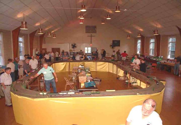
This has been the usual layout for the CJSS Get Together for the past 6 or so years. My yard is the straight
section on the left. Earlier CJSS
Get Togethers had the church hall filled with the layout including a wye
section and a branch line. The straight section on the right is thought to be
the worlds first S Scale module. They are owned by Mike Ferraro, and are about
30 years old now. It features 3 levels of switching and 3 different code rails.
Control Panel
This is the control panel before we added DCC on the left. It
view also shows the hinged lid. On the right is after DCC was added. You can
see the red panel light in the upper left that is wired hot to the track power.
If there is a short, the light goes out. You can see this from across the room.
You can see the 4 wire plugs on the front for the local cabs. We only used them
for 1 or 2 shows. I also added a nice fold down tray to hold the DCC handles
and DCC cab port in the front.
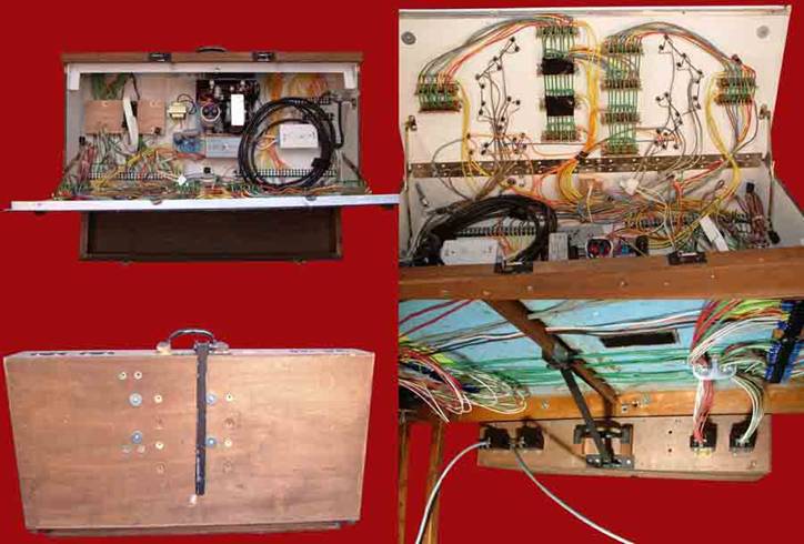
Here are 4 views of the control panel. The upper left shows the
power supply in the center. The DCC power booster gets mounted to the left of
the power supply. The upper right shows the panel back side with all the
wiring. This was the bulk of the work to make this module to the S-Mod
standards. Again, DCC makes this wiring
all but obsolete. The bottom left show what it looks like when folded up. At
the bottom right you can see the large plugs to connect the control panel to
the modules.
(See next page)
Updated 2-25-18
All
photos and content © Lanes Trains 2005-2026