|
|
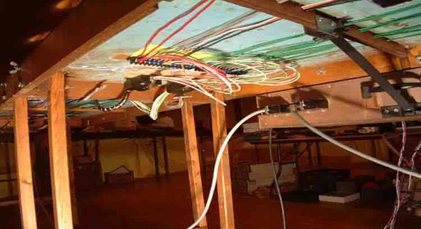
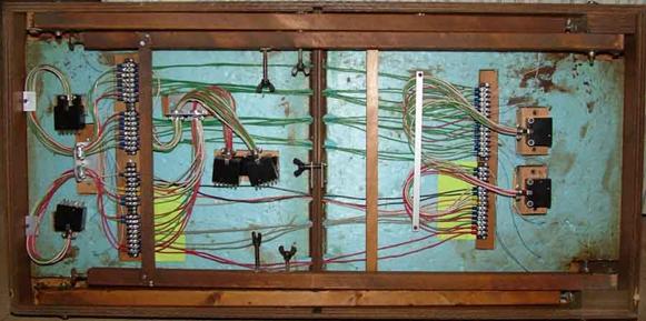
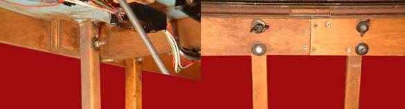
Page 2 Control Module This is the underside of the main 4’ module. You can see the control
panel bolted on at the right. You can also see the diagonal brace for the
panel, so there is no need for a leg for the control panel. Also note the
large plugs for the power bus joining the sections together, and the patch
cords for the turnout power plugged into the control panel. Since this
section has 4 legs there is a spacer block for this set of legs to fold
inside the other legs.
This
is the underside of the main 4’ control module showing how the legs fold
under and lock in place with the same bolts used for setting the modules up.
|
|


Look Don no
bridge rails!
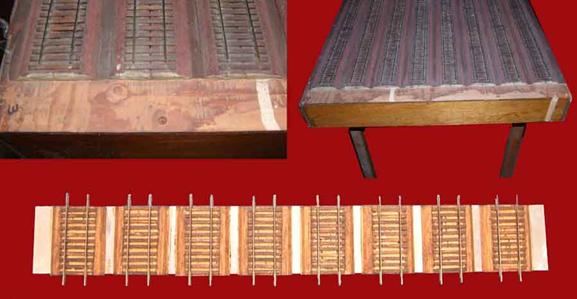
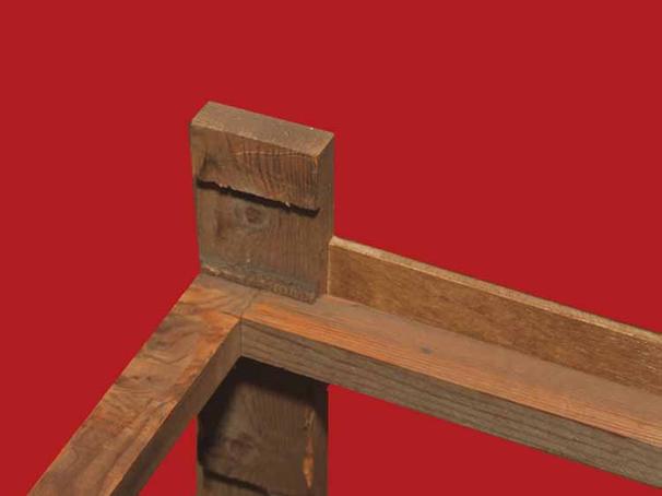
The
upper left is a close up of the cut back roadbed. The upper right is an
overview of the module ends. Note the dowel on the right that keys into the
next section for instant alignment. The bottom is the bridge rail section that
is made from sheet aluminum and custom made wood roadbed.
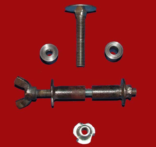
Hardware
Here is the hardware I used. The top is the “elevator bolt” for
leg levelers. On both sides are the bolt bushings I had made so that any wear
will always be metal to metal and not wear out holes in the wood. Next is the
bolt bushings and wing nut head bolt that I made. These bushings are ¼” pipe
and washers welded together. At the bottom is the “Tee” nut used for threading
into wood. I drill holes in the flange of the Tee nut and use ¾ “ nails for additional strength.
This view on the left shows the spacer block for the sections with
4 legs and the large multi-conductor plugs. The right photo shows the module
connection joint.
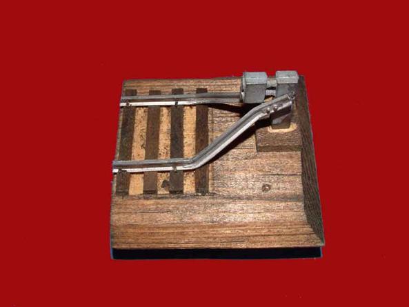
This is the removable track bumper section. The bumper is a
Lehigh Valley Models kit. There are 4 nails that pin them into position.
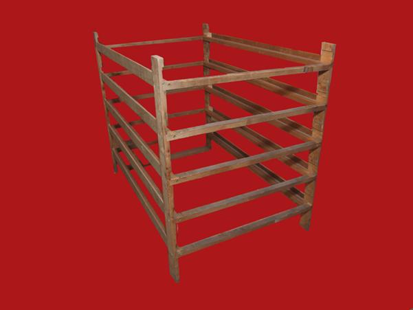
Bakers Rack
This is the “Baker’s Rack” I made to stack the modules in for transporting
them in my SUV. I have a 2003 Ford Escape. They also hold the modules for
storage when not in use. It is surprisingly light and strong. The largest piece measures ¾” x 1 ½”. Note the use of Dado
joints wherever possible. That is why the unit is so strong.
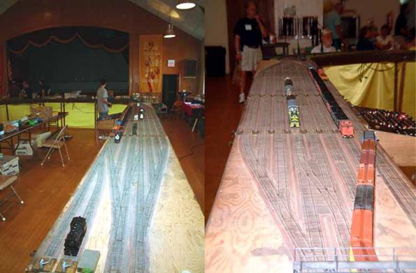
This
is both ends of the yard ladders. You can see the joiner bridge rail sections in
the right photo. There are 2 removable Lehigh Valley Models track bumpers
(lower left) I have since painted the bare plywood areas Tuscan because that is
what I had in my airbrush that day.
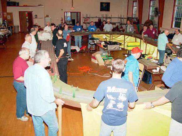
CJSS Get Together 2006
No, it was not Hands Across South Amboy!
The church hall roof was leaking right on my yard module. Don Thompson directed
the attendees to move the entire assembled layout 3’ to the other side of the
room! You would have missed it if you blinked. The trains left on the layout
did not even derail! The leak in the roof stopped shortly thereafter!
Updated
2-25-18
All photos and content © Lanes Trains 2005-2026