|
|
I
am not doing Solidworks designing for others anymore. I may be able to give
you some tips on how to do it, but by far the best thing to do is learn it
yourself and make your own parts and designs. No one knows what you want more
than you do. The learning curve for Solidworks and designing for producing 3D
master patterns is absolutely massive though.
|
|


The
following is the page archive of when I was actively doing designing, and a lot
of the items I made for me. It is extremely outdated at this point. In August
2024 I got back into doing my own 3D printing so even the text on 3d printing is
very outdated as well. I have made truly 100s of parts not shown here.
When I first heard about Solidworks I knew there had to be some
model railroading applications. I have previously made brass masters the old
fashioned way by machining a brass pattern 4% oversized. It is a VERY time
consuming process. The worst thing about it is, many times during the making of
the mold; the master pattern can be damaged or totally destroyed. So when the
mold expires, the part cannot be reproduced again without a new master. I have
had that happen to me. This process has been replaced with Solidworks and a
Rapid Prototype printer for producing master patterns.
The simplified key difference between AutoCAD and Solidworks is
AutoCAD is just a 2D drawing. With Solidworks, you can send the file to a
number of different end processes that will manufacture the part. It is a 3D
MODELING program. Solidworks is also very flexible, in that an item can be
easily modified and revised after the initial creation of the item.
See below for the master patterns I had made from my drawings. It
is really a truly amazing process. The quality was outstanding.
Prototherm and VisiJet are 3D printing materials I have used.
Prototherm becomes the master pattern for a lost wax brass
casting mold where you have a mold made for traditional lost wax brass casting.
This has a glassy smooth top surface for great finish and resolution – on ONE
surface.
VisiJet is a burnout material. It is for very low production
items. No mold is needed. You get a 1 cast part per SLA printing because it is
burned out in the curing of the investment plaster. My venture into using
VisiJet was not as successful as I had hoped. What is considered an acceptable
VisiJet parts surface by industry standards once it is burned out and cast was
by far not acceptable to me. It is good for utility
parts like motor mounts that are not seen or for difficult to cast parts, but
you will spend extensive time sanding and smoothing the brass part surfaces.
I model almost exclusively in brass, so
brass casting is the most likely way to go here. If you are modeling in
plastic, then of course you just use the rapid prototype produced plastic part
as is, but that would be very expensive!
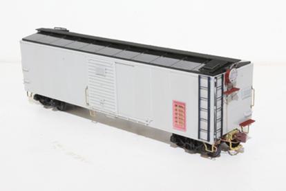
In November 2013 I made a Seaboard
express boxcar that had a
large vent in the side of the car. I had some vents made in Prototherm and used
them as the final use parts. It is the first time I have used a 3D printed item
like this and it worked out very well. Still I would NOT do this on a wear part
of something that is highly susceptible it handling. I do not know if the parts
can become brittle with age. Since the vent was completely painted I am not
very concerned with any issues happening later.
See the end details of my Solidworks
2 Page for
more details on getting urethane items made.
See videos of the 3D printing SLA
process on YouTube here (about 2 minutes) and a longer video here.
I HAVE 10
years of “dream parts”, the parts I never thought I would ever get - in my hands
now. I am making new parts all the time.
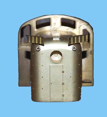
P70r
Roof Vents
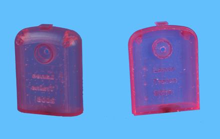
The
Penn Ventilator
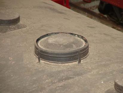
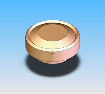
Capped
Vents
(I
call them stumps!)
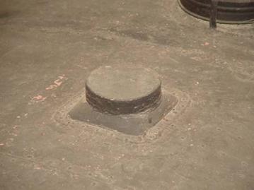
Penn
Ventilator and Capped Vents Master Pattern
This
material is called Prototherm
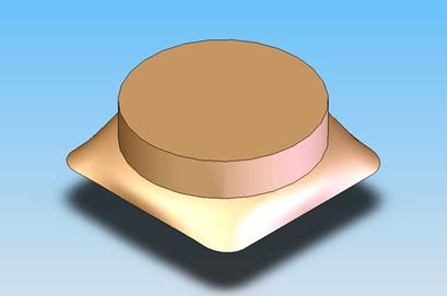
Motor
Mounts
(Made
from VisiJet)
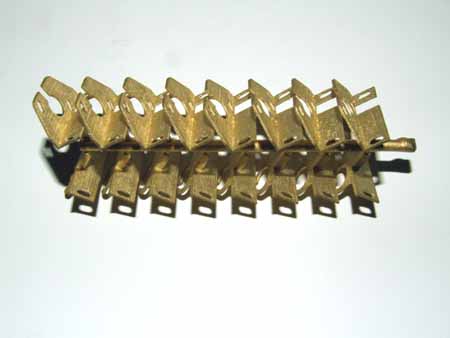
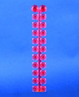
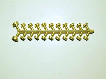
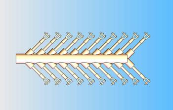
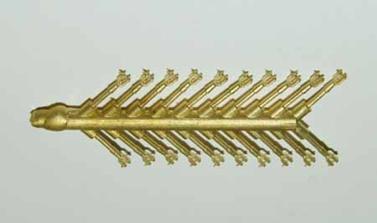
Steam
Engine Handrail Stanchions
(From
the I1)
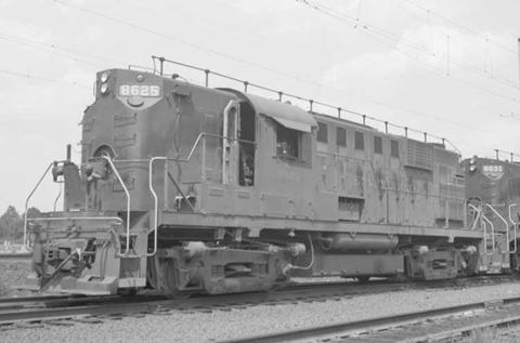
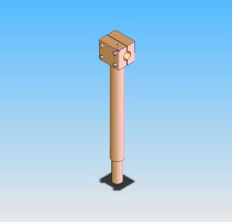
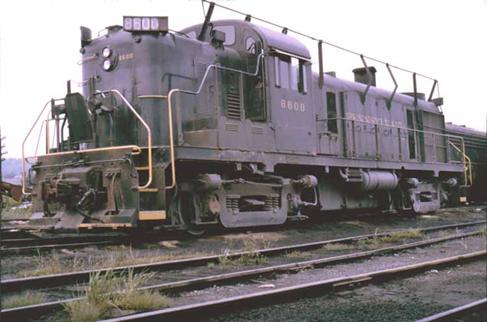
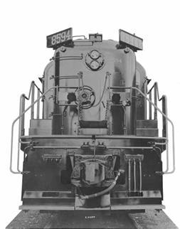
RS11
Antenna Stanchion
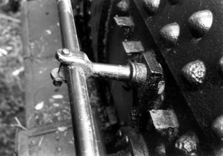
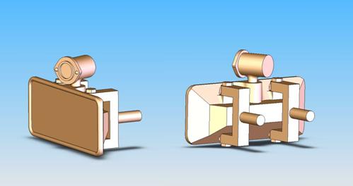
Sound
Cam Wiper Assembly
While
none of this was made using Solidworks, it looks SO nice
when drawn in 3D!
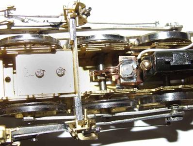
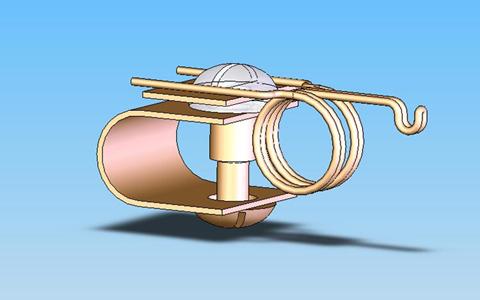
This is mounted down in the
frame right behind the sound cam on a new cross member soldered to the frame.
The approximate dimensions are 3/8’ wide x ¼” high x ¾” long. The bottom wheel
plate is between the brass screw and the C bracket. You can adjust the pressure
of the wiper finger on the sound cam from the bottom
of the locomotive without ever taking it apart.
RS3
Numberboard
Actual
3D Printed Master
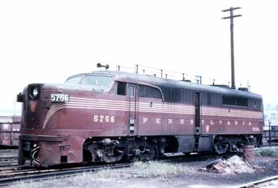
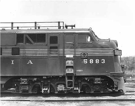
PRR
PA1 and E7 Modern Numberboard, Brackets & Marker Light
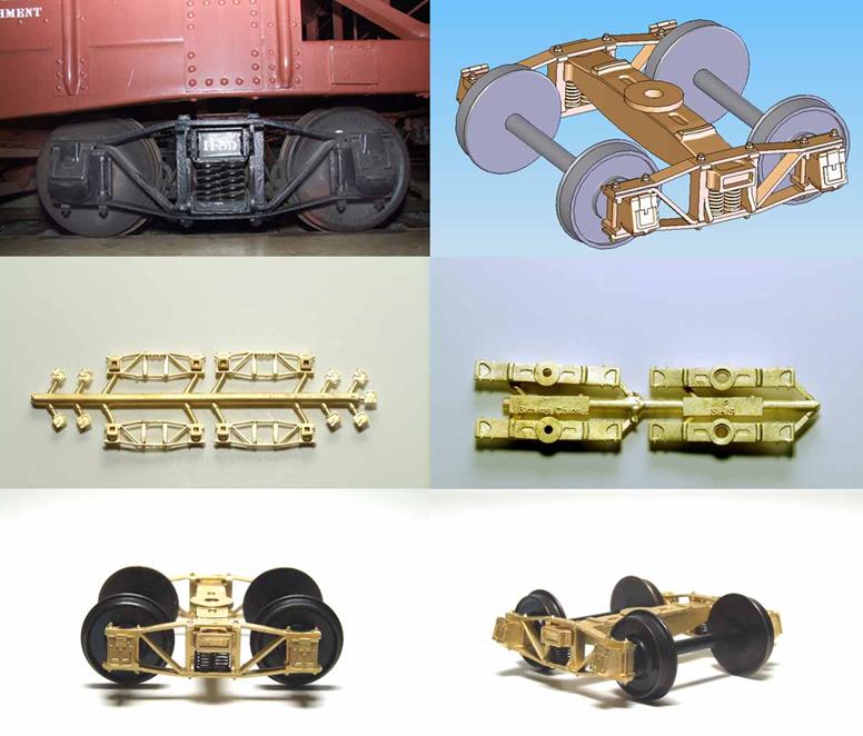
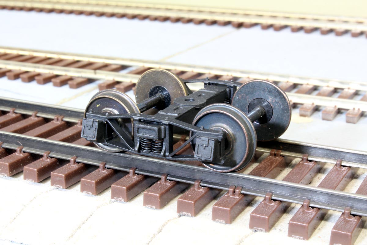
PRR
2D-F1 Archbar Truck
This
is my biggest success so far. More is to come!
This
truck is now available from Pennsy S Models
The
2D-F1 truck was used on FM GL, GLa, GLb, GLc GP, GPa, GR, GRa, GS, GSa, GSd, H22, K7, XL, X23, X24, X25, X25a and GSC. It was the predecessor to the very common
2D-F8 truck.
These
trucks have never been offered previously in S Scale in any form. It was done
as a design challenge when I was going to school for Solidworks. I measured a
real 2D-F1 truck on the GLa hopper at the RRMPA in
Strasburg PA, and then compared my sketches to real PRR drawings I have. I
crossed the prototype details and features of S Helper Service trucks to design
this truck. So it is essentially a brass S Helper Service truck that uses their
Delrin axle bushings and wheels. NWSL premium code 110 Nickel Silver wheels fit
in perfectly as well. I am not sure if P64 wheels fit. They roll and equalize
VERY well. The bolsters have the same ride height as the SHS trucks when using
33” wheels. The castings include 4 side frames and 9 journal box covers (1
extra) on the first tree. The second tree includes 4 bolsters. 1 bolster pair
is for generic installations like brass cars. The second bolster set is
designed to fit S Helper Service cars. Assembly and some drilling out of holes is required.
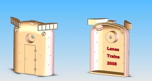
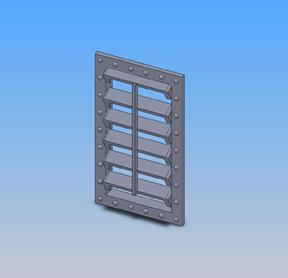
E7
Vent Door
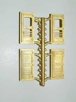
Vent
for Seaboard Express Boxcar
Updated 11-29-25
All
photos and content © Lanes Trains 2005-2026