|
|
On
January 2, 2011 I started to make my “permanent” layout in my basement.
Trains were running 10 months later after some extensive work. My
layout is S Scale standard gauge. I had some thoughts about trying to have
some East Broad Top in the 20+ years I was somewhat randomly buying and
building trains leading up to actually having a home layout but then reality
sets in. There was not enough room for any narrow gauge. The
layout footprint is 12'-6" x 35'-4". The layout is 30” wide
throughout. Easily accessing trains on the layout was very important to me so
I operate from the outside looking in at the layout. I
spent a significant amount of time thinking about and testing for layout
height. I wanted to make it as high as practically possible. That makes for
more storage space under the layout and easier access for wiring and repairs.
There
are no “kids” coming here to see trains. I do not have any kids
just dachshunds. My nieces and nephews are 30 to 50+ years old. That can be a huge mistake when building a layout that is too low for “kids” to
“see the trains” that never actually come to visit or the owner’s kids likely
with minimal interest in trains anyway grow up leaving the layout permanently
lower than it ever should have been built. That can lead to a tear down and
rebuild of a new layout that is higher. I
measured my eye level while sitting in a wheeled drafting high chair I have.
I made a layout test section that was 3” higher at first then I cut it down
when I measured train clearance at my armpit while reaching to the back of
the layout. The trains just cleared my armpit. It was all DEEP thinking I
tell you! |
|


I
am 6’-2” tall. The layout is now 54” + - to the top of rail on the mainlines which I consider to be the perfect height for
me. About 4 years after the layout was built I was told about measuring “nipple
height” on the builder is perfect – sort of like everyone is supposed to know
that “rule”. I checked and that is completely true for my decided layout
height. How coincidental was that?
Added 5-17-20
I
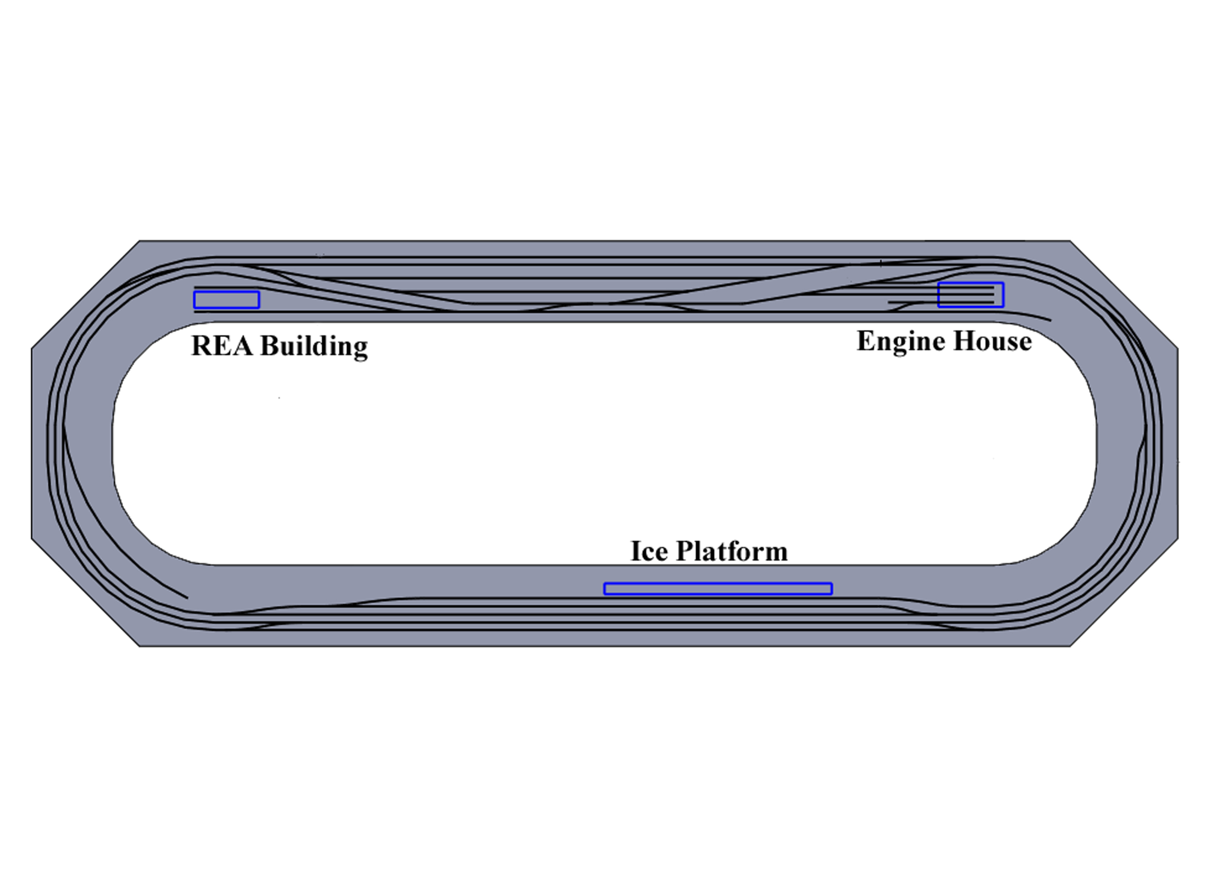
was nudged to make a track plan of my layout. The radius are
nominally 63”, 60” and 57”. Doing the plan was fun but took about 6 hours.
Luckily 1 of my Solidworks computers is right next to the layout. Trying to get
the plan right was a challenge.
I
don't claim my layout has any real railroad track design practices. I started
with 16 feet built by someone else and made the rest. It does run reasonably
well. I regularly run 40+ car trains. This is likely all of
the track I am going to have. Any more track
then this would get too congested. There is a large addition I have had in my
head for many years but that is probably not going to happen.
Unfortunately
the screen shots in Solidworks are not the best resolution but I got it done.
It is rather accurate in scale. I did some extensive measuring of the placement
of the track.
Click on photo for larger view.
Revised 11-4-20
In
November 2020 I added another mainline crossover making this the final track plan
extremely likely. Too much track is not good. I have to have some room for
scenery!
The
following pages are the history, designing and building of my layout from day
1. Maybe there are some design ideas you might like for your layout. The text
that was written at that time is shown on the pages remains mostly unchanged
even though some of it is wrong now because the plans and layout design have
changed. A lot of the designing was “make it up as I went along”. There was not
a master plan from the beginning followed.
Getting
a house with a basement also came with a major dose of reality. The plans for my 20 + year long dreamed about
but very unrealistic plan of modeling “Wildwood to Pittsburgh” layout died the
very second I walked down my basement steps for the first time while first
looking at my house in June 2009. The basement was much smaller than “the
dream” but I was somehow completely OK with that. It was truly a life changing moment at that exact second I realized this could be MY basement and this is what I was going to be
working with. In 30 actual seconds I was satisfied and said I wanted to get the
house. Reality and in some sense maturity had finally arrived at 40 years old.
I
quickly settled in on the idea of building something generic, manageable and
moveable (sectional) but not built to S-Mod Standards. It will be higher and
have sections that are larger than I could easily move for a weekend train show
set up. I had to get trains running in a reasonable time frame to keep my
interest and progress going.
My Layout
Getting started
February 2011
This
large S –Mod module was purchased on eBay on 10-7-06. It was Don DeWitt’s
former Grand Arbor yard module. In January 2011 I flopped
the modules down on my basement floor to see where I should start. All sections
are 30” x 4 feet. The track plan was modified a bit from Don’s original design
by Jack Bartman the 2nd owner. I am now the 3rd owner.
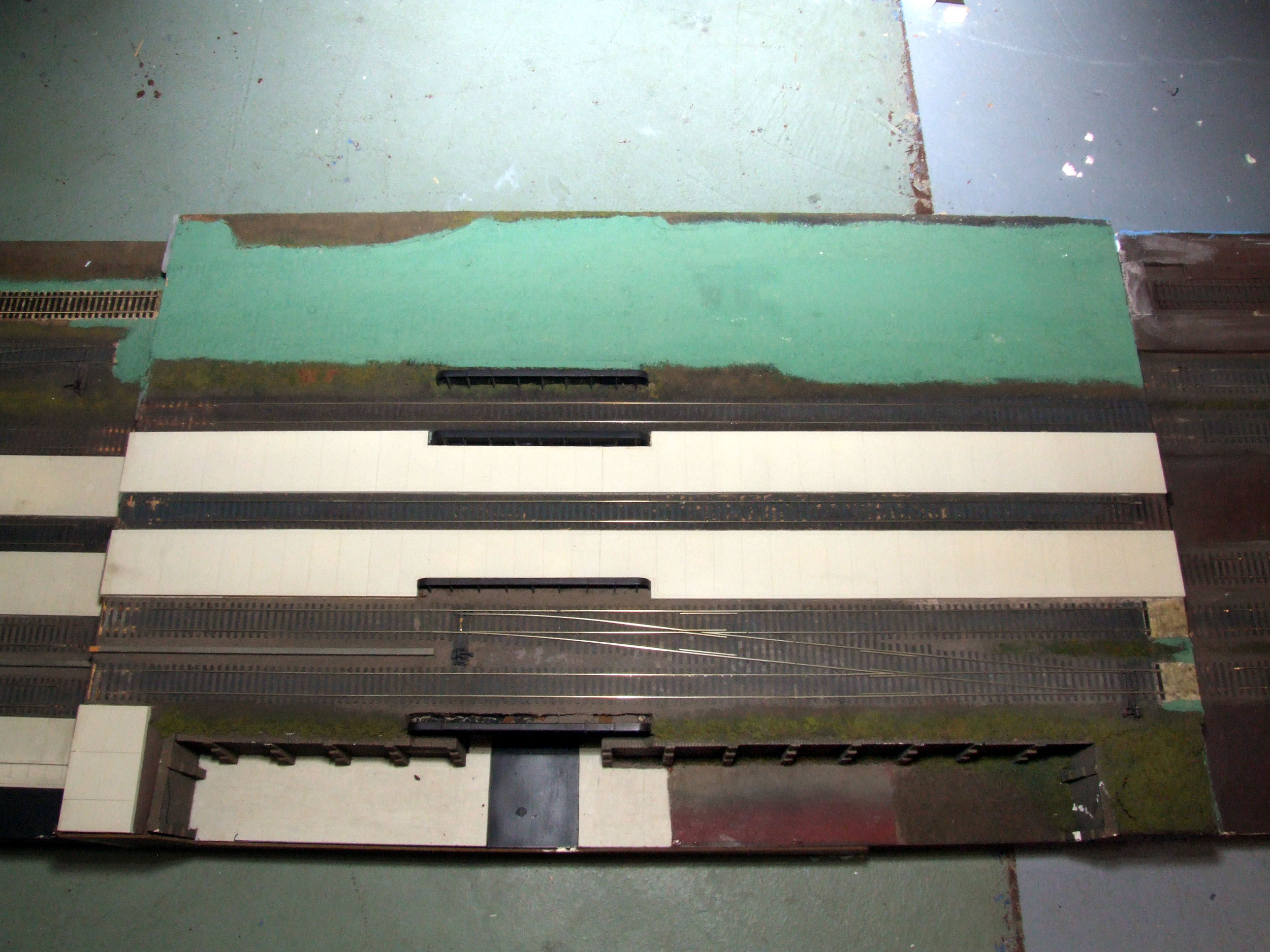
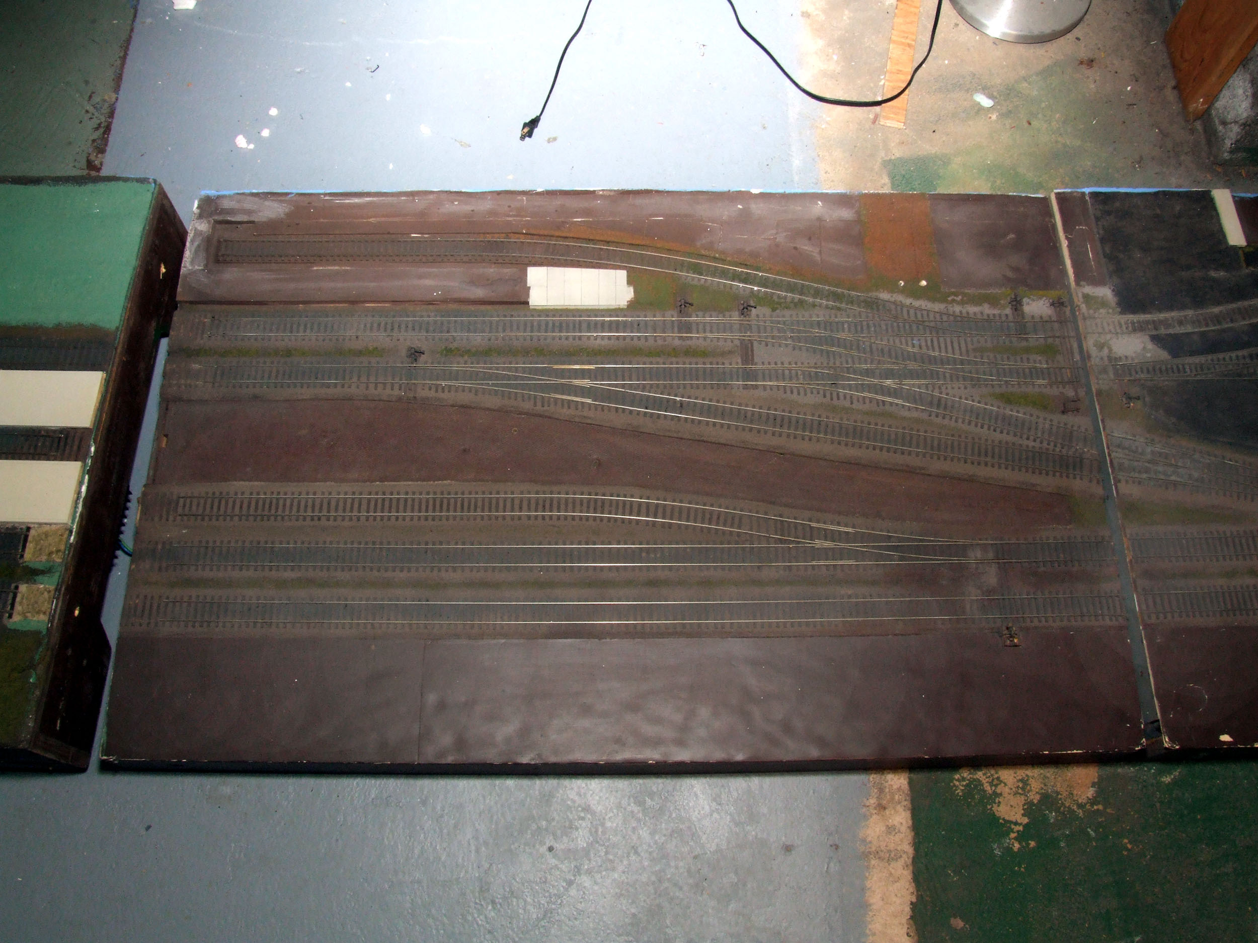
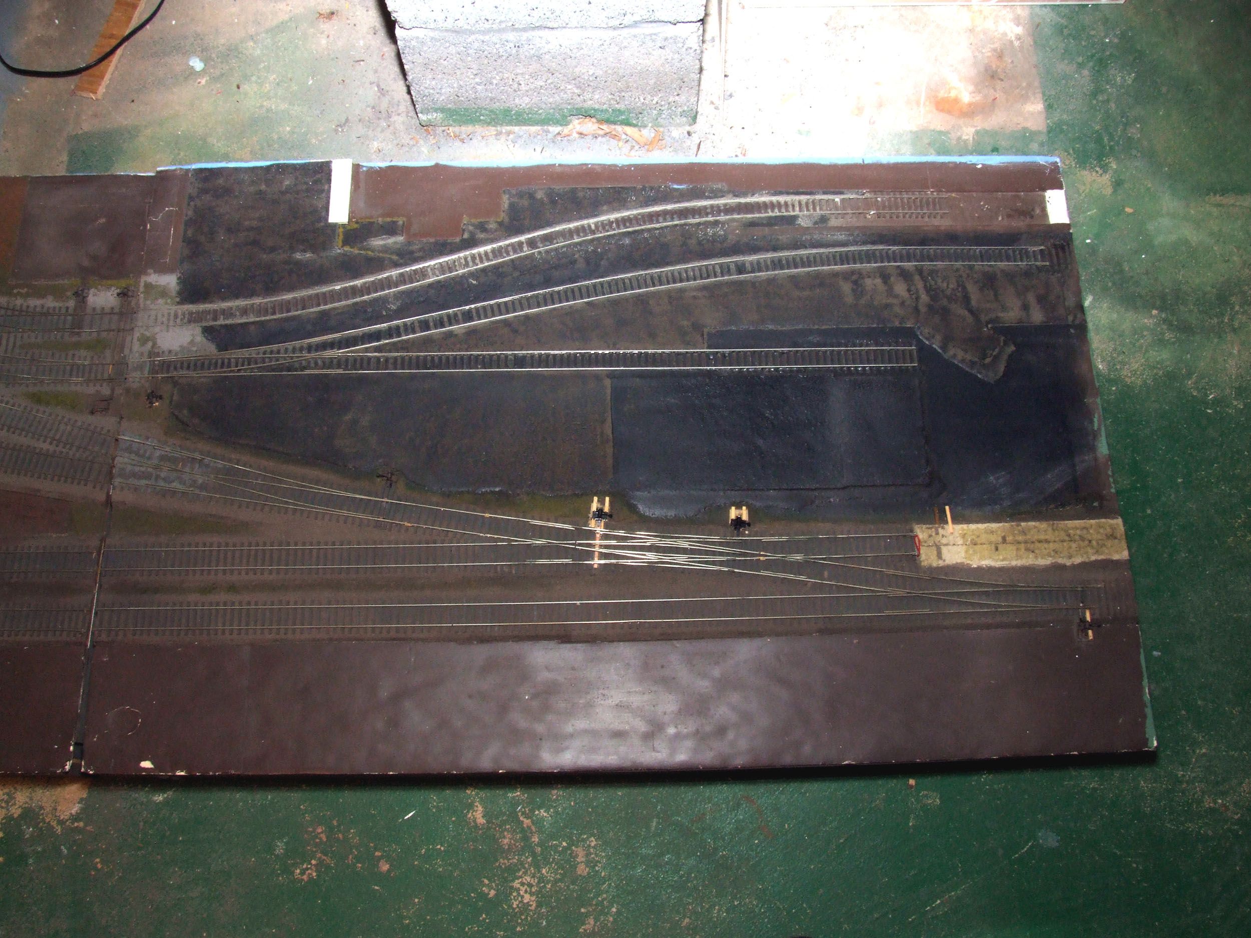
These are the sections shown left to right. All tracks were code 100. Even for the last 2 sections at right of
Don’s design that remained intact I did not understand the use of #4 turnouts
to enter or exit a passenger terminal. A
double slip switch just seemed like it could be a place for constant
derailments as well. Rule #1 for my layout design is all my locos I own can run
on any track without derailing. The #4 turnouts had to go. Since I was powering
my turnouts having a crossover on a bridge would be a problem to make powered.
So the decision was made to not use 8 feet of the original Grand Arbor and make
all new. Those 2 sections were eventually sold. How I modified the sections are
shown below with photos added 7-17-11
I am using 16 of the original 24 feet for my layout. It will
basically be a large loop for now with a footprint of about 12 feet by 35 feet.
That will take up MOST of my basement. My straights will be 24 feet long. A
freight yard will be the basic theme of one side. A passenger station will be
the theme of the other side. The mid 50”+ radius turns will accommodate every
locomotive I own. The track height will be about 52” from the floor. Besides
the 16 feet being refurbished everything
else will be made brand new. With the work
done so far I have wondered if I just should have just started out completely
new but I am beyond that now. It is a rolling work and idea in progress – get
trains running in my house! I am using S Helper Service flex track (Code 139)
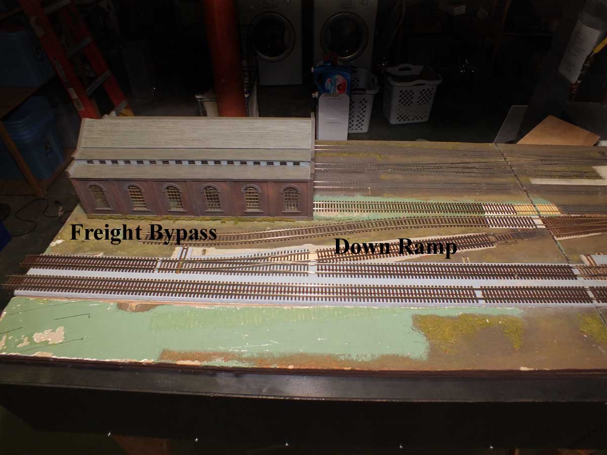
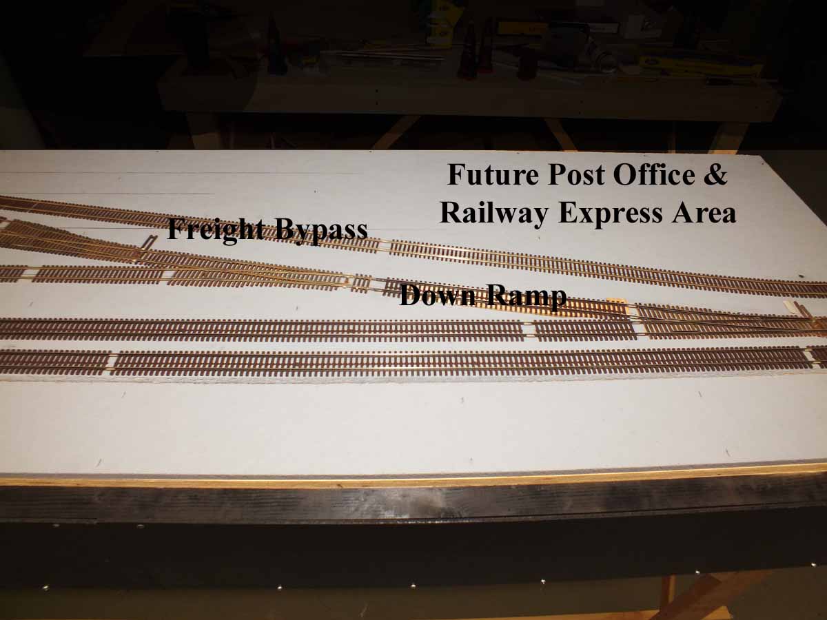
elevated on ¼ ” thick Homabed for the mainlines. Everything
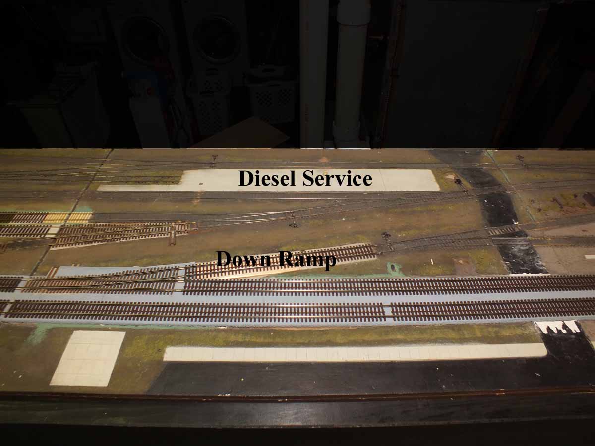
else is code 100 flat on the deck. “Down ramps” have been made to transition
between the elevated mainline roadbed and change of rail sizes.
Both ends will have 2) code 139 mainlines and a code 100
runaround/yard lead. This will be so the mainline trains can run unimpeded
while keeping switching busy. There is a “freight bypass” route on the
passenger side. Of course I will be using NCE DCC with wireless handles. There
will be 3 power regions with many sub-regions protected by circuit breakers.
All turnouts are going to be powered with the Switchmaster/Hankscraft stall
motors. They will be controlled with DPDT toggles on the running fascia track
diagram/control panel with bi-color LEDs to show route direction. I believe in keeping things simple especially if visitors come over and
want to run.
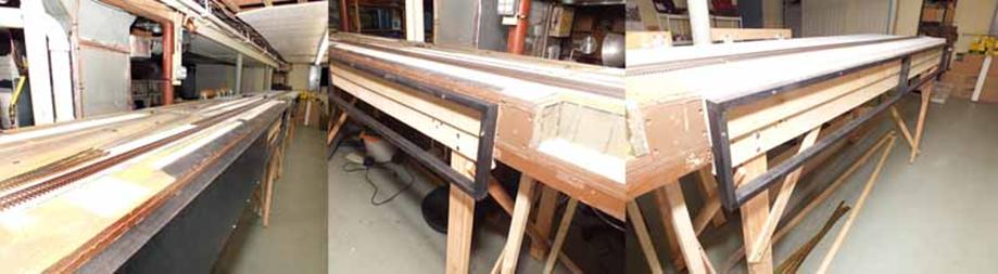
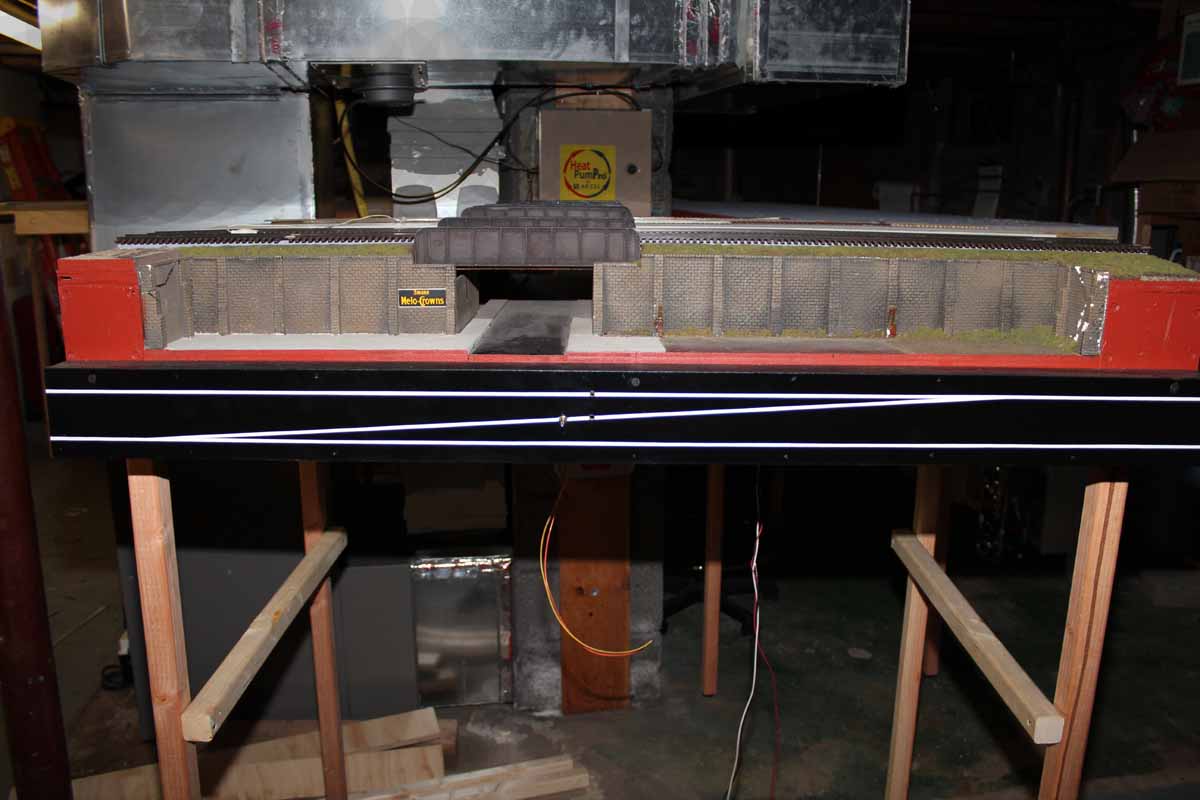
Here
are the control panel frames being constructed.
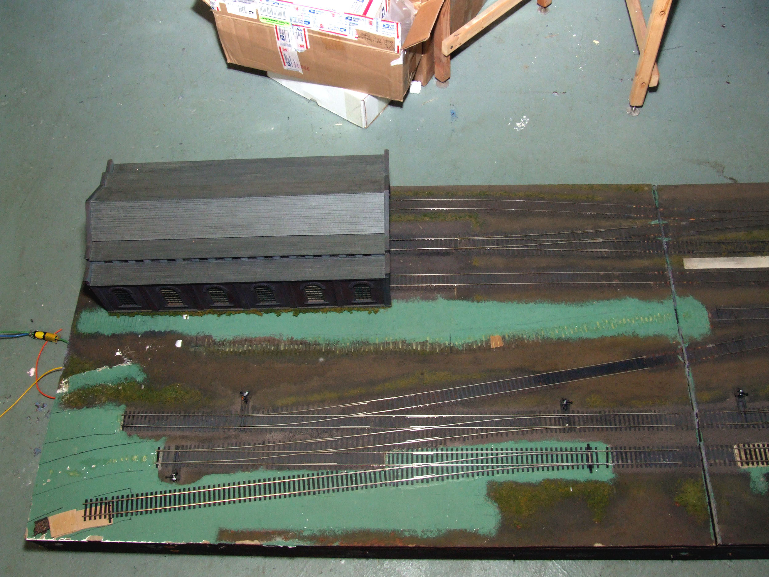
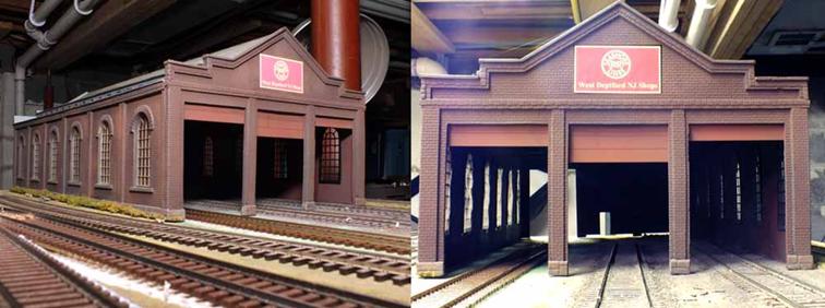
Some
people have asked me about the engine house. It is a plastic O Scale trolley
barn kit made by Korber. I bought it from Don DeWitt after buying the yard
modules. I HAD to change the sign to something PRSL.
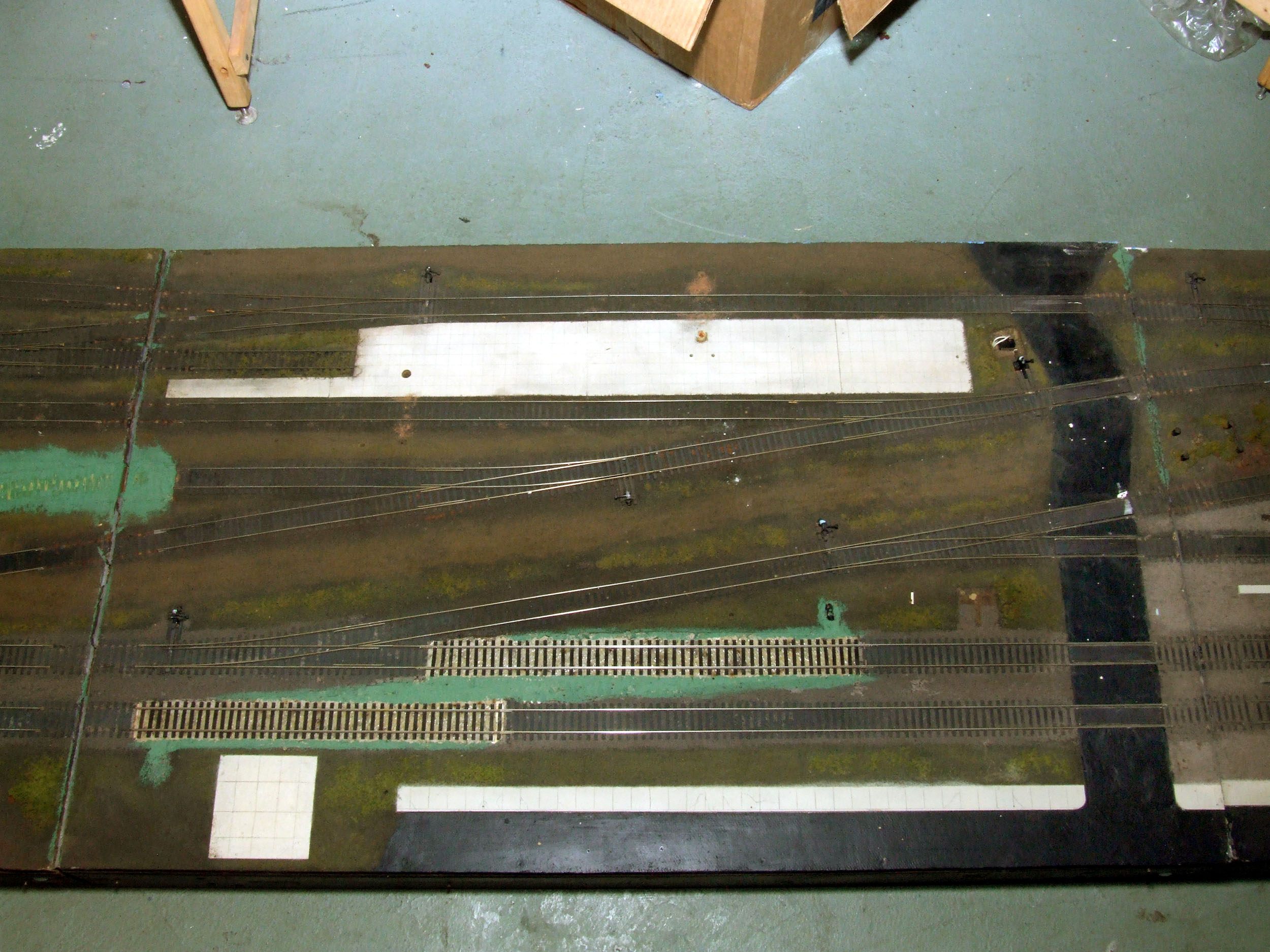
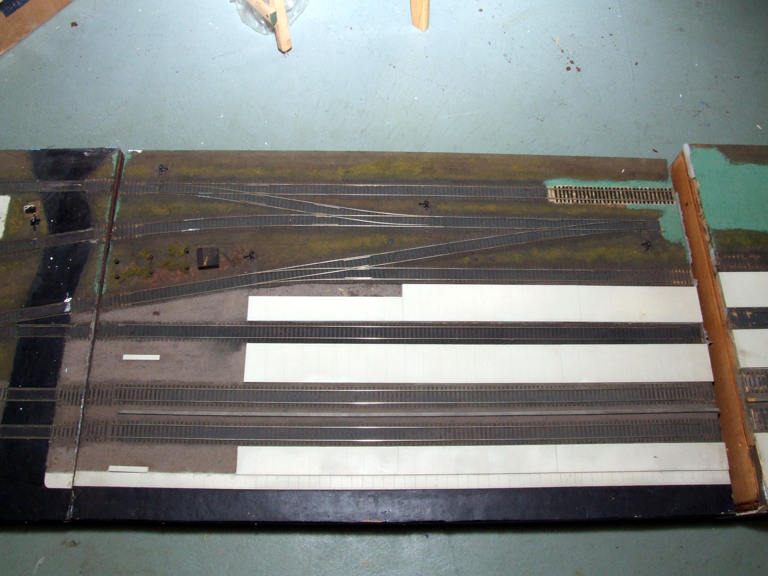
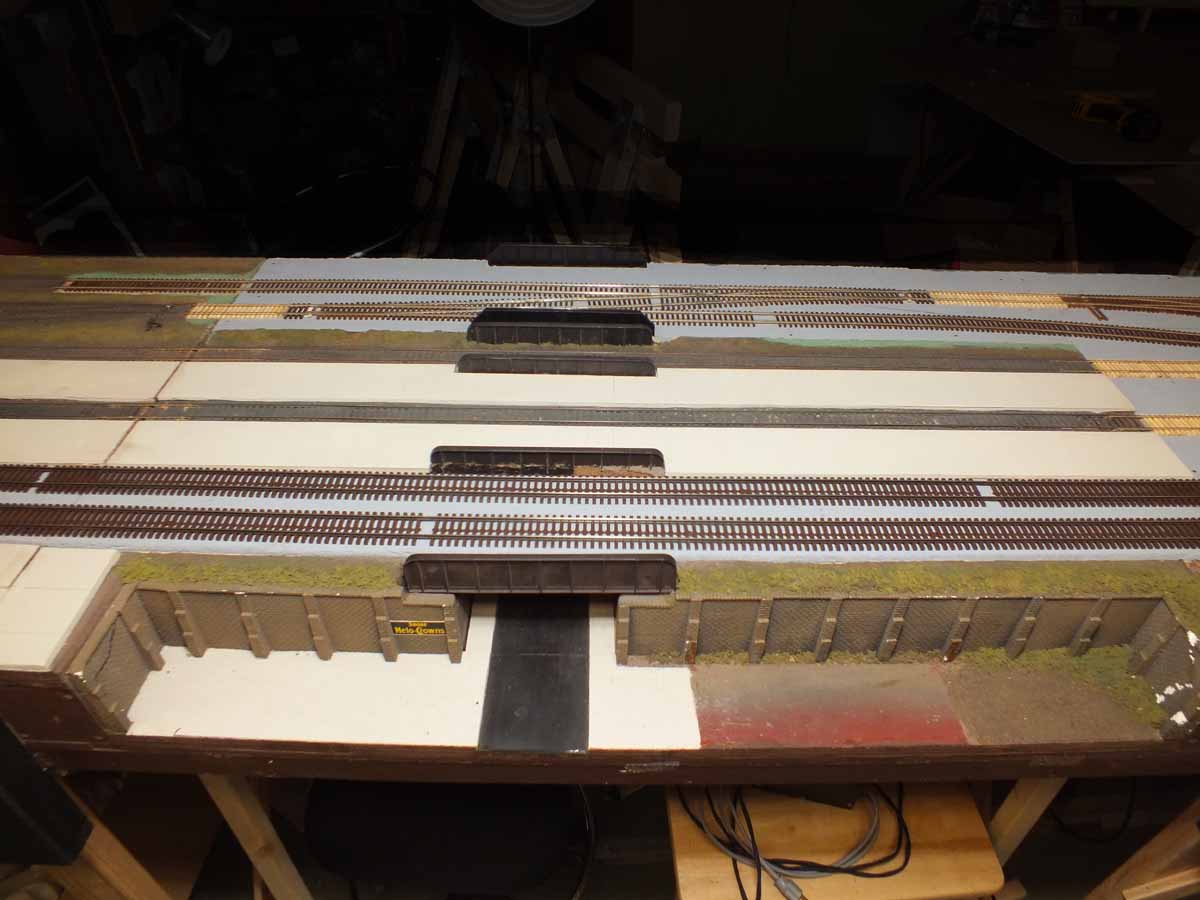
Photos added 7-17-11
They show the sections in order left to right.
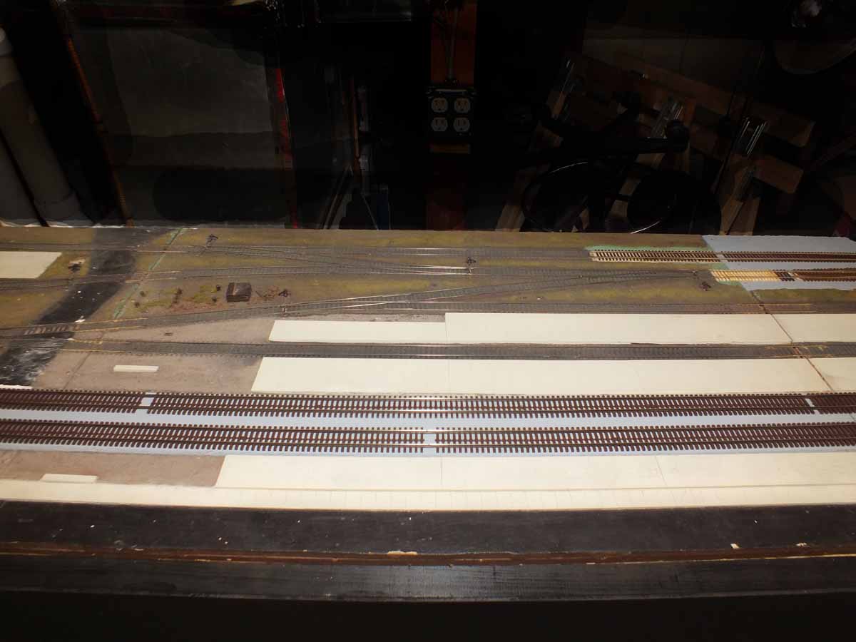
The
white panels are sidewalks for where the passenger station to going to be. I am
adding about 4 feet to them on the new section to the right.
The Corner Frames
Added 7-21-11
There are a few possible
pinch points in my basement. No matter how well I try to plan everything I just
don’t know for sure until I “see it
live” full size on my floor. Before diving head first into making the rather
elaborate frames I wanted to cut some “flop down” sheets in the footprint of
the corners to put on the floor and see how and where everything will go and
fit. I have heard of people using large sheets of cardboard for this purpose.
Luan worked just as well which is what I used.
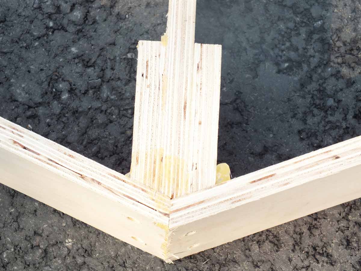
Since the inside frame
rail is going to be curved, I could not figure how to hold everything in place
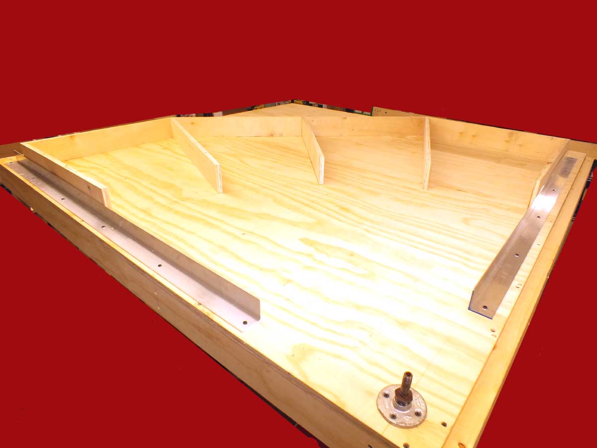
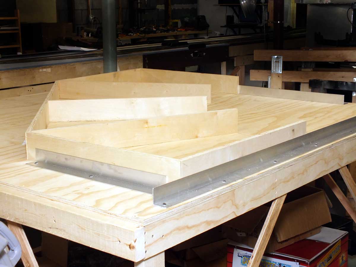
with the pressure of something curved. I decided to make a frame fixture that
will hold the pieces in place while the glue dries. I made a temporary 70” x
70” work table that will be an assembly fixture.
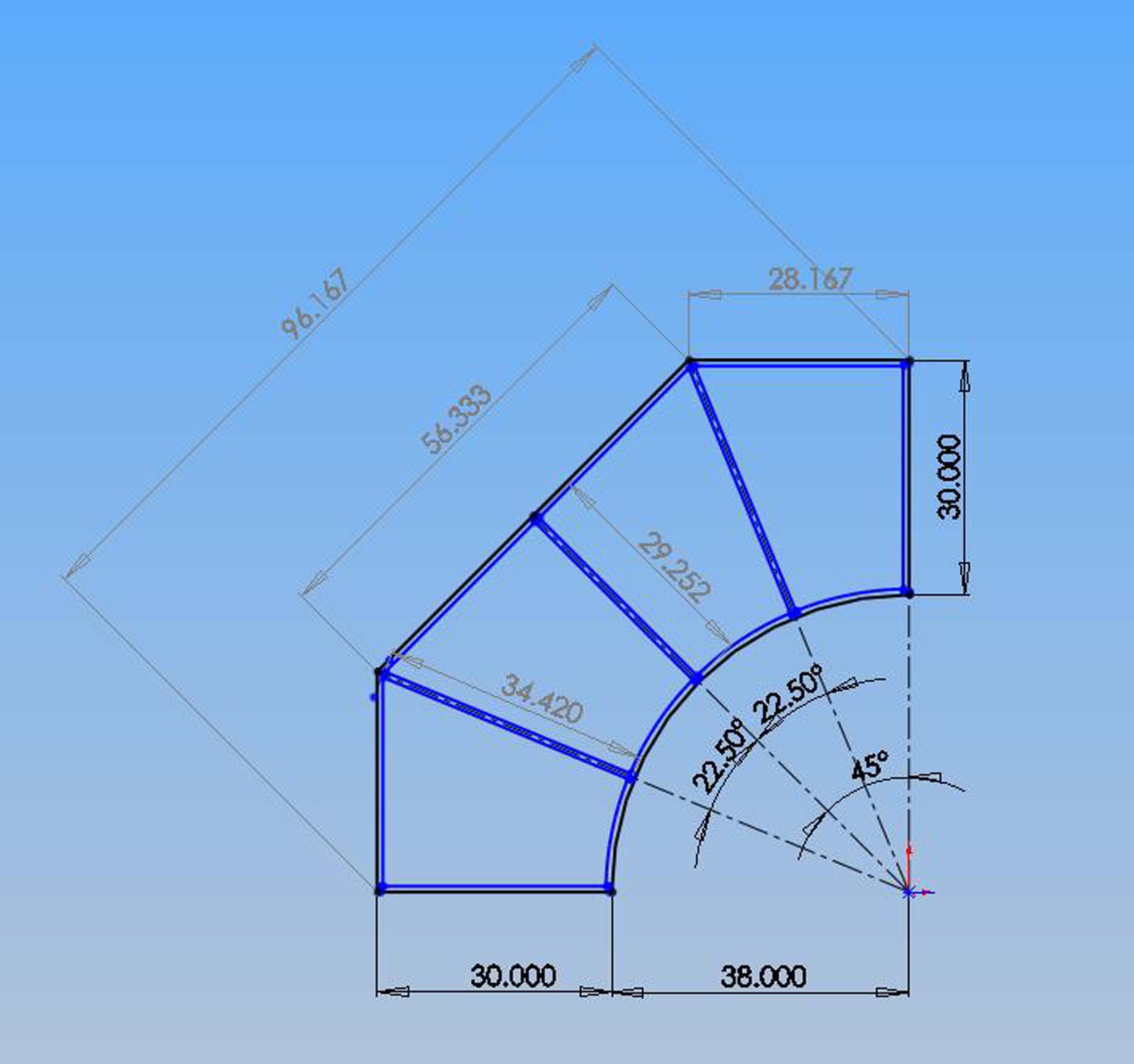
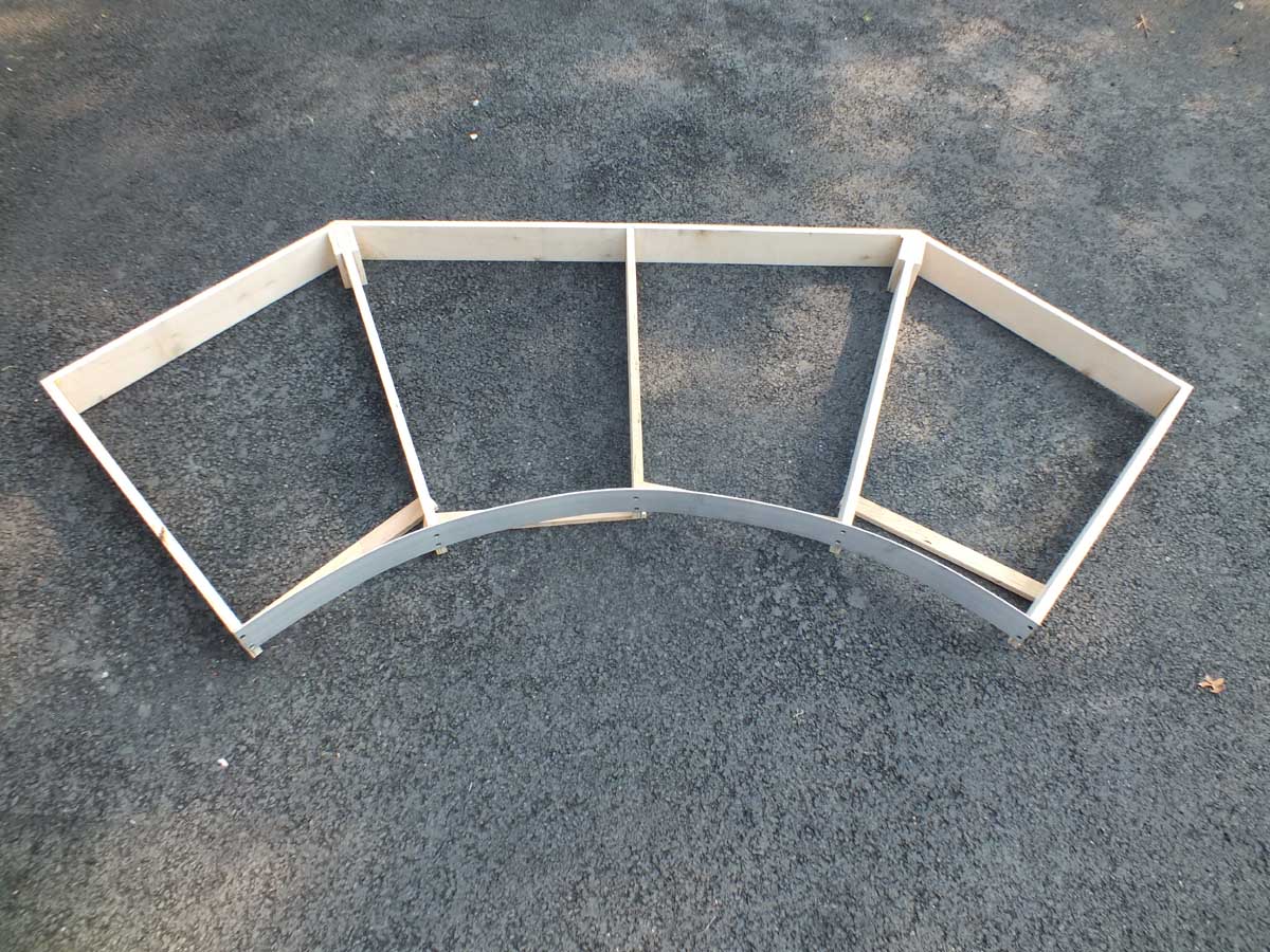
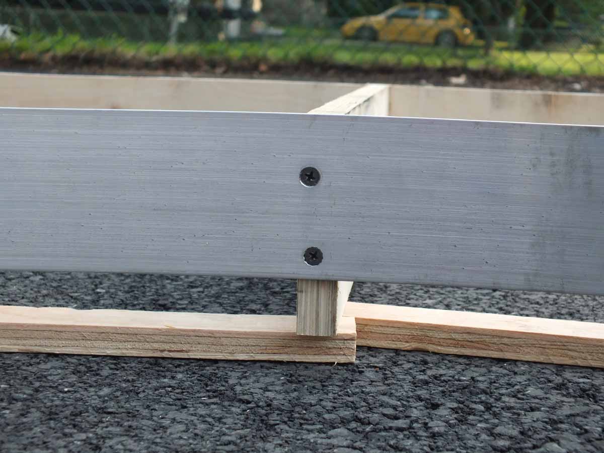
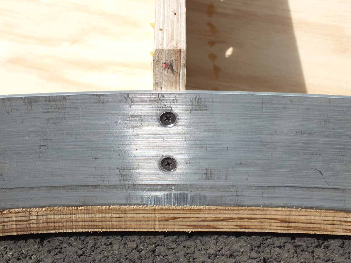
I designed the frame in
Solidworks but only used 2D. Everything can be measured to 3 decimals places if
I wanted. I would have NEVER been able to figure this out without Solidworks or
a computer design program. I was going to try and bend plywood as the curved
back rail, but decided to use 1/8” x 3” aluminum flat bar.
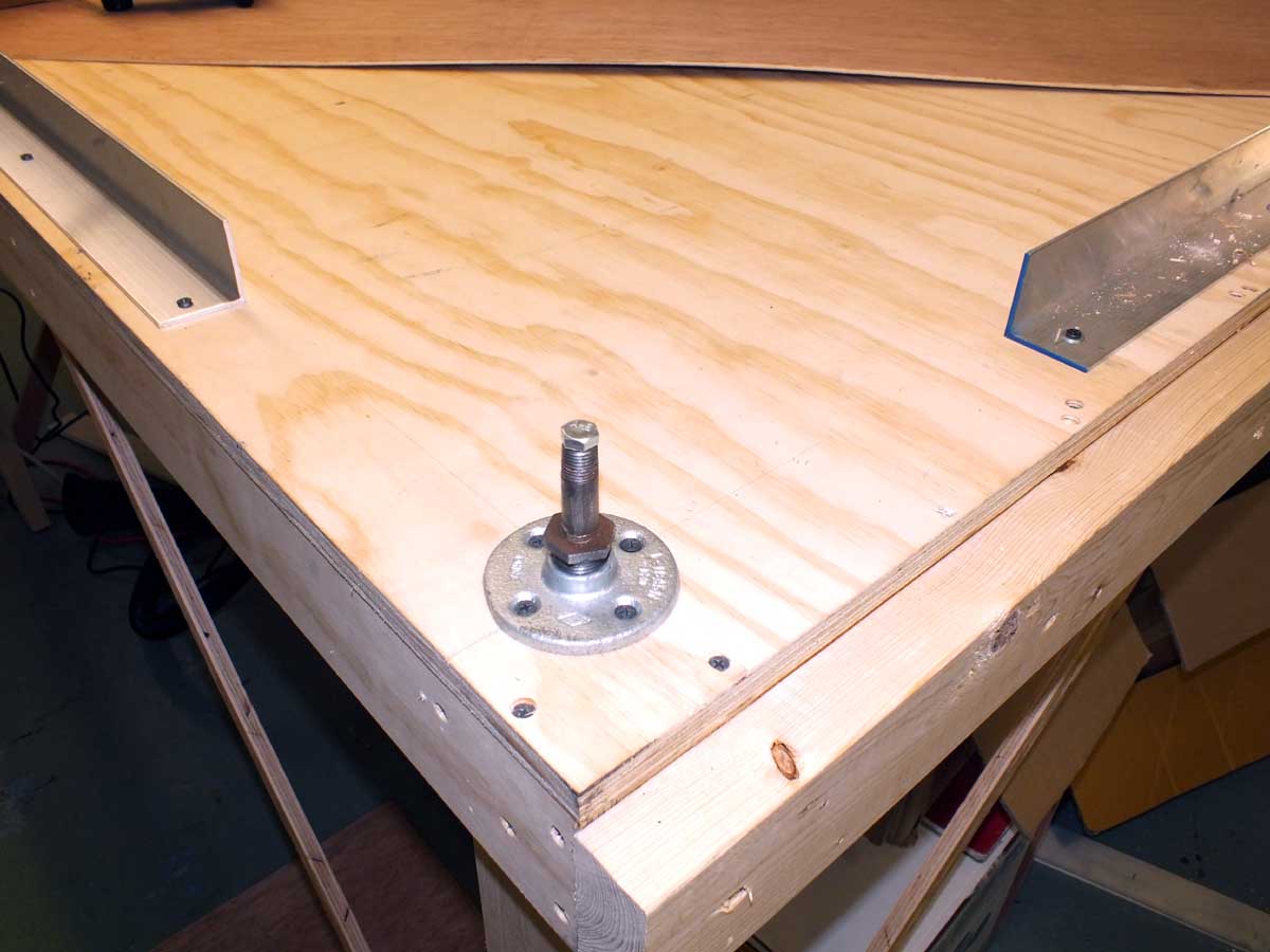
Below is my work table.
With the exception of the above frame plan I almost never fully
plan or draw anything I make. It is usually figured out on the fly. I like to
do it that way because it keeps me thinking. The pivot is a 1/2” pipe floor
flange that is reduced down to 1/4” pipe. It will eventually have many braces
to make it into a full holding fixture.
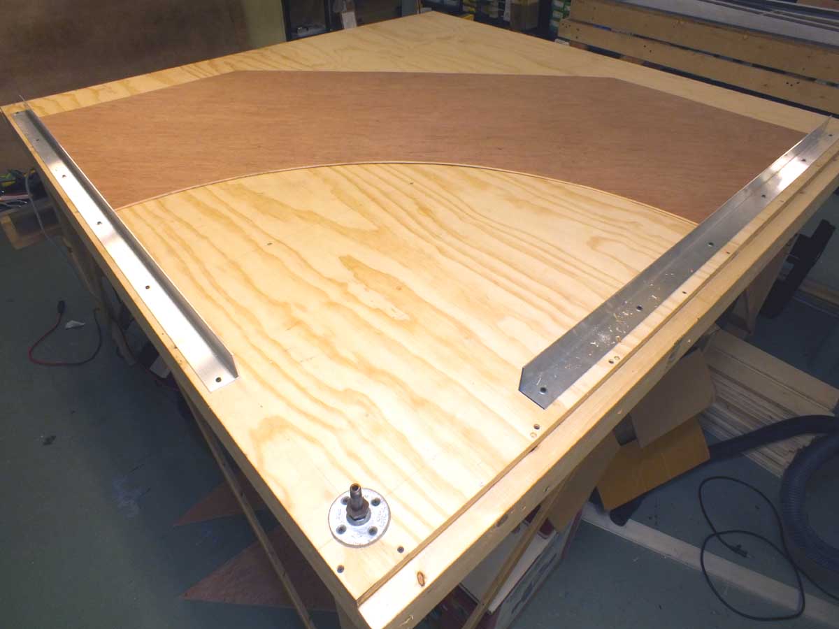
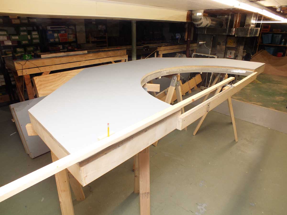
The below photo at right
is the first sheet of luan I cut out in the footprint of the frames. I think it
kind of looks like a baseball field! With the exception of the curved side
edge, I cut everything with a utility knife and long steel and aluminum
straight edges because I wanted all of the cuts to be crisp and straight. There
was also no sawdust generated in the basement.
The first sheet turned out
to be well within
1/8” of all needed
dimensions and angles. I dare say they
are within 1/16” or LESS!
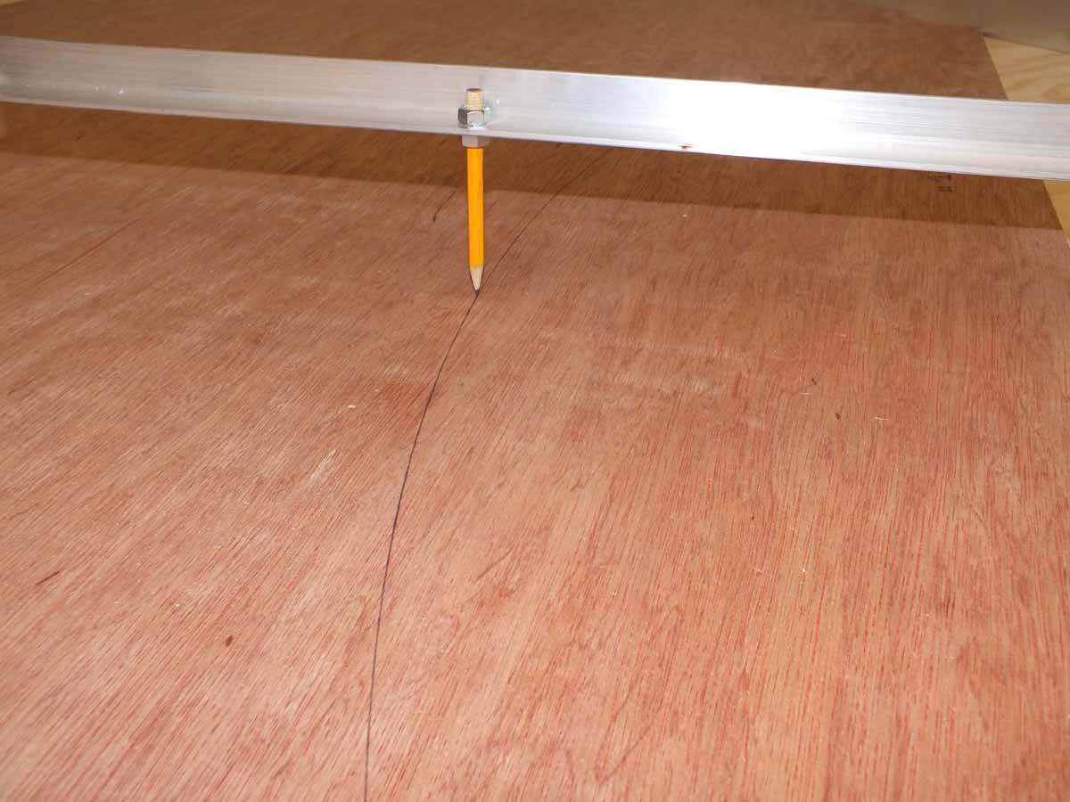
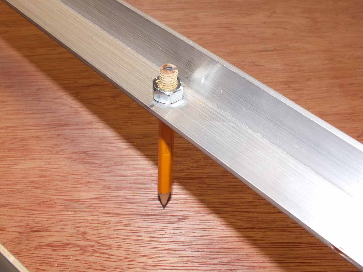
The “compass” is a piece
of 1” aluminum angle. I was rather proud of myself when I thought of the
“pencil bolt” idea to secure the pencil for its simplicity. I just ran a 5/16”
nut down the pencil. Problem solved!
7-26-11
I am starting to lay out the first corner frame. I am very happy
with how it is turning out. The measurements are really close to the plan. I
have to tweak some of the lengths of the frame pieces but not more than 1/8”.
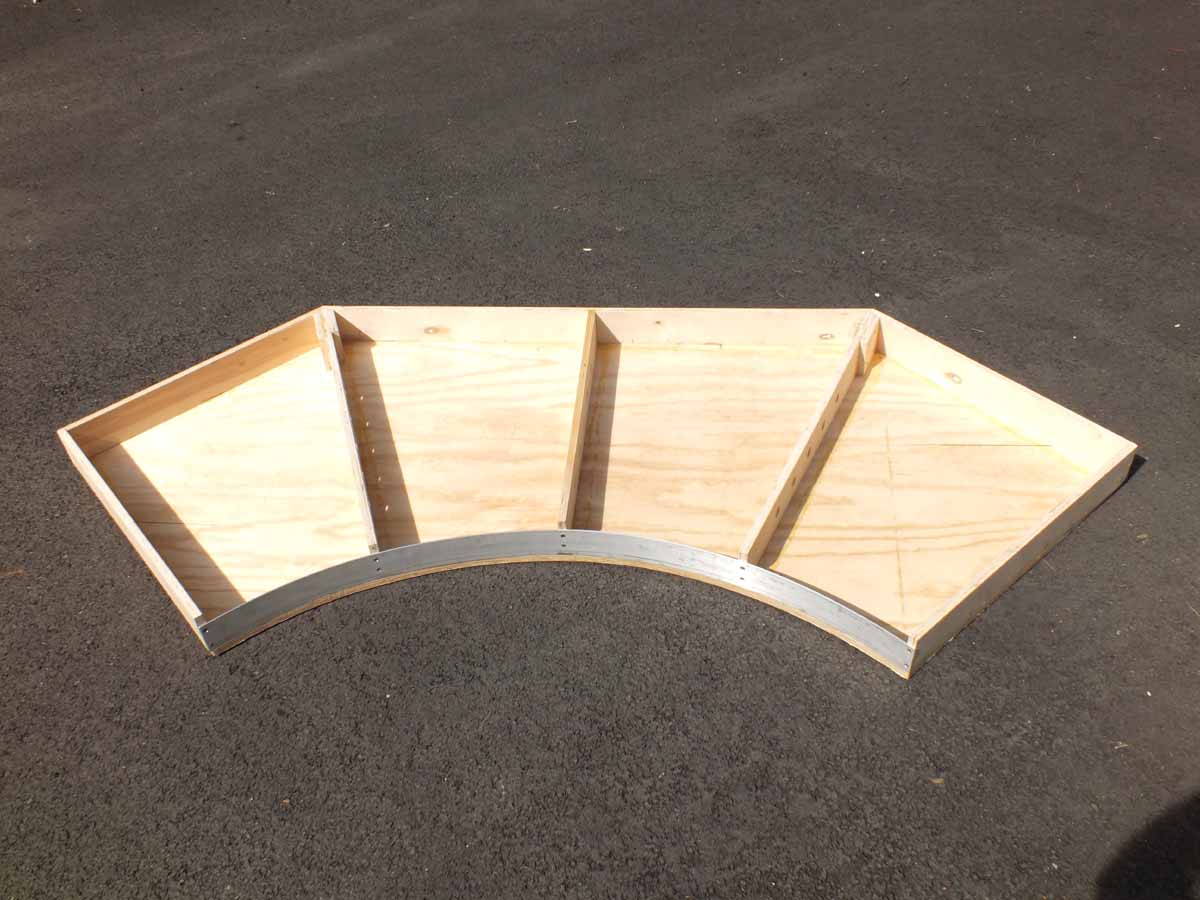
Added
8-11-11
This is the first corner frame I completed on 7-29-11. I
photographed it in my driveway
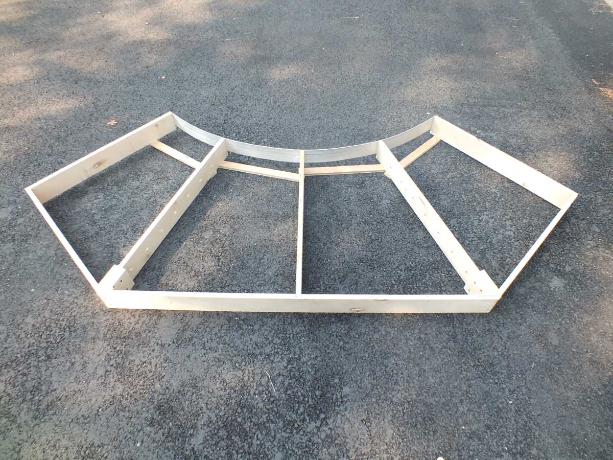
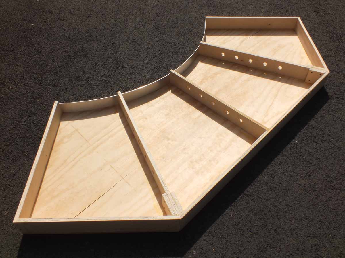
Added
8-13-11
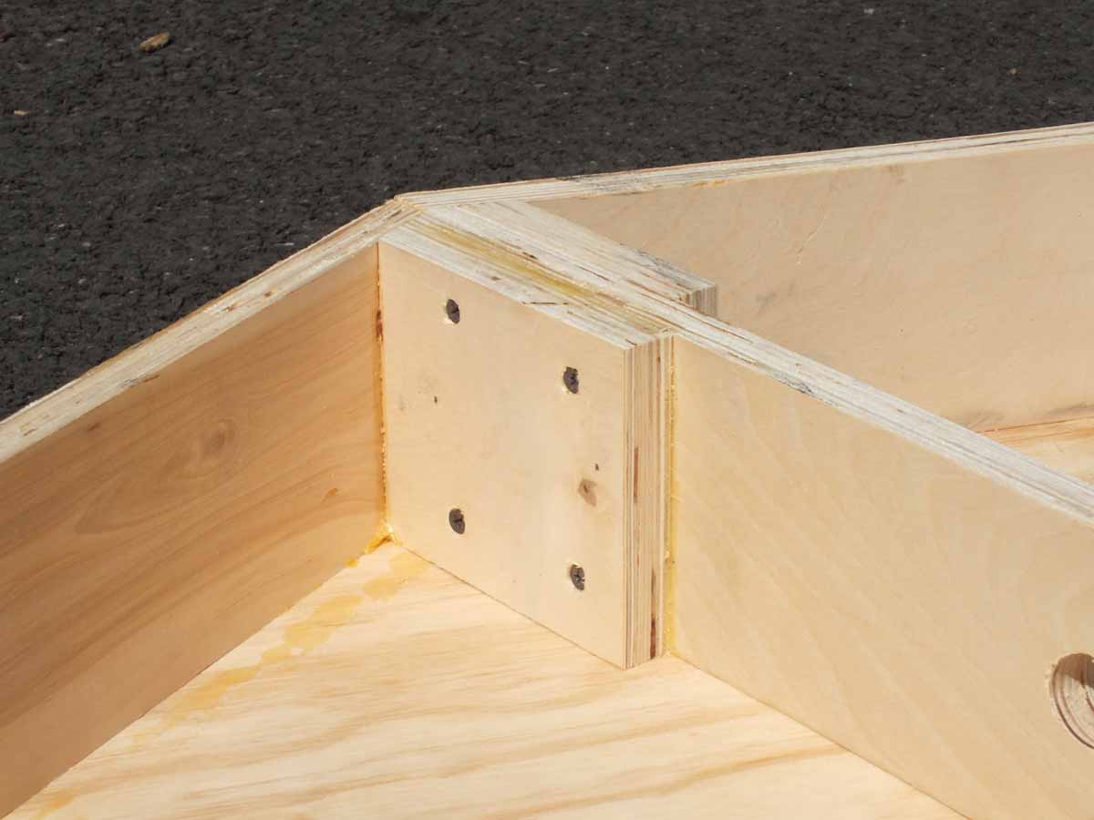
Here are the basic frames completed with the ¾” deck installed.
I have all 4 of them built to this point now. I rough cut the curve with a
saber saw and trimmed the deck with my router and a flush cut bit. The corner frame fixture has since been
dismantled as soon as they were completed and returned to the wood pile for
recycling into future projects.
Added
10-16-11
In the 2 months since my last update I worked on the layout extensively without
much documentation of the progress.
I just figured I would the spend time working on the layout
instead of photographing and updating this page.
As of 10-16-11 all sections are up on their real legs making a
deck height of 53”. All of the above frame construction photos were on a work
table with the legs not actually attached to the frames at 48” high. We flipped
the sections vertically and back to horizontally MANY times during the wiring
process. This would have been very difficult with legs attached.
The mainline track centers are approximately 3” throughout the
entire layout. While 3” was a little wider than I would have liked the main
purpose for building the layout was to be able to run anything I
owned on any piece of track without concern of derailing or sideswiping
another train. The track centers had to be wide because of the EM-1 boiler
overhang running on the inside main possibly hitting passenger cars on the
outside main.
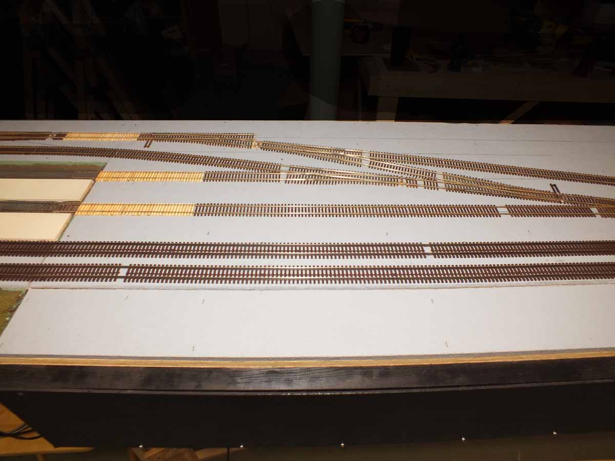
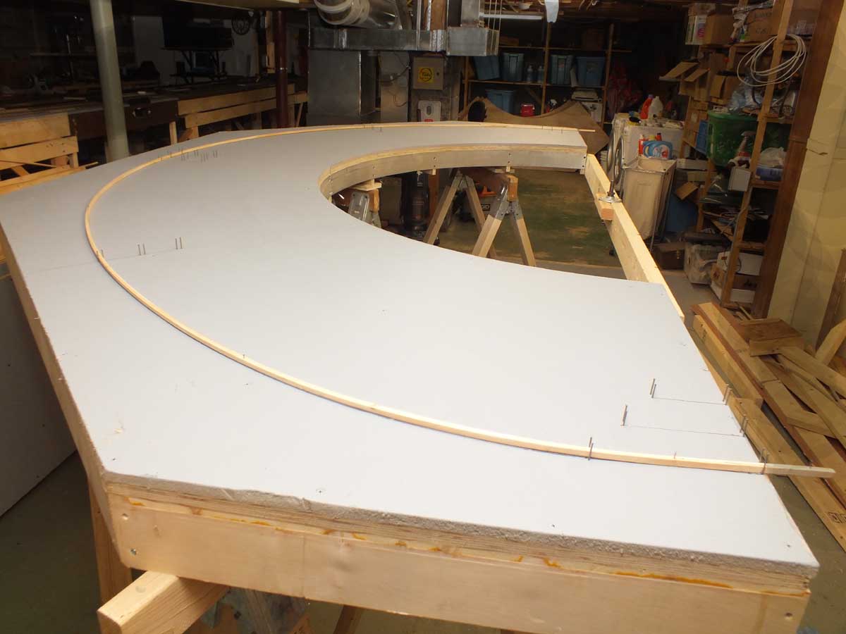
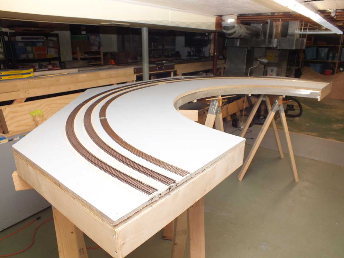
These photos are showing the laying out of the curve center
lines. I did not use the compass to draw fixed radius. I used the compass to
just lay out starting reference points. In the middle photo below you can see
where I used long wood splines (pine cut to ¾” x ¾”) that created a flowing
constantly changing radius with easements etc. I tacked in a few needed points.
The natural curvature of the wood did the rest making the laying out of the
center lines very easy as long as you don’t force anything. Making the 18’ long
splines was annoying. They broke a few times during the layout of the lines but
the results are well worth the effort.
The radius is nominally 62”, 59” and 57” for the 3 curved
tracks.
Wiring
I should have taken photos of the underside when I got the
modules. Everything was done by the previous owner in white
wire. Tracing a wire was impossible. As with any project like this, especially
wiring things are expected to go wrong. My friend Charlie Leonard is helping me
greatly especially with the wiring and finding shorts. After truly months of
trying to figure it all out I got frustrated and just cut everything off.
Finding one of the shorts on one of the old sections I refurbished was
particularly frustrating. We still don’t know how or why there was a wire UNDER
the boards of a grade crossing. That is where the short was! Unbelievable!
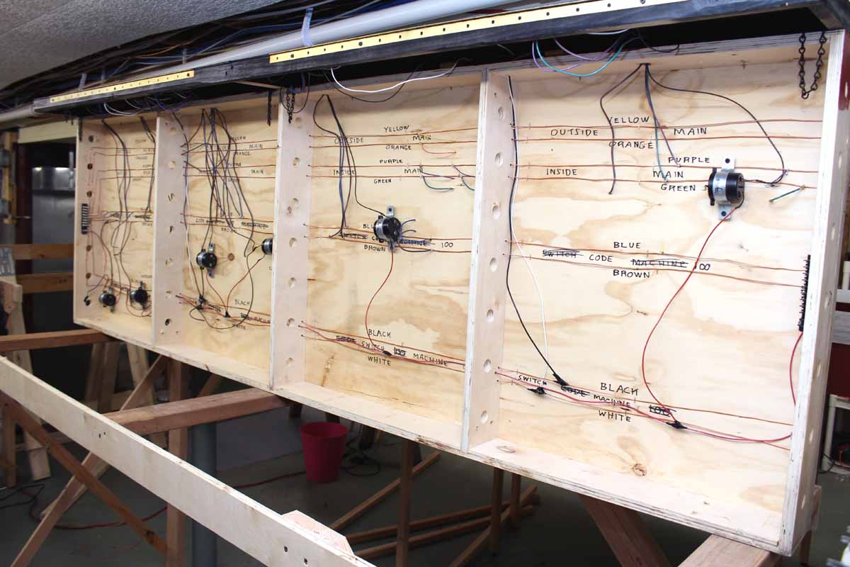
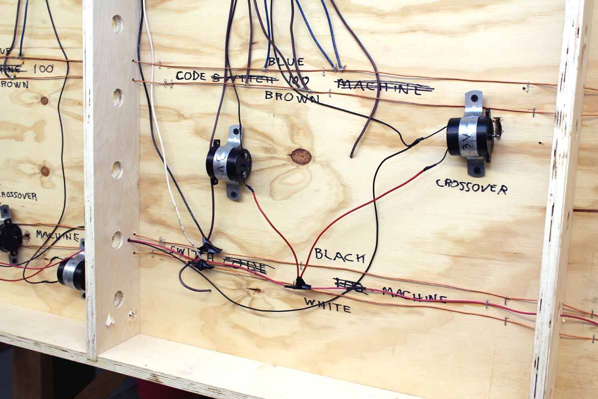
These photos show the wiring the new 8’ long section showing the
bare 14 gauge copper wire buss lines, turnout motor power buss, and Hankscraft 3
volt 1 RPM stall switch motors running at about 2 volts. With that gear
reduction they are unstoppable at full voltage. It is rather typical of what
the rest looks like. ALL turnouts are powered except 1 that is getting
spiked shut. There is no need for anyone to reach into the layout for ground
throws. There are now 9 wires running the entire length of the underside of the
layout. 6 wires are for the DCC power buss for the 3 power regions. Three wires
are for powering the Hankscraft motors as plus, minus and center tap. We have
completely isolated the frogs but they are powered. The control of the motors
and flipping the polarity of the frog is all done at the panel with a single
DPDT toggle switch on the panel. Crossovers require a triple pole double throw
toggle switch.
Bare
Wire Buss
I am likely the only person that opted for using a bare wire
buss. Lots of people said not to do it they have to be twisted pairs. Since I
was going to solder everything and not use the suitcase connectors that I heard
fail having insulation on the wires was a problem. Finding a roll of 14 gauge
bare wire was a challenge at the time. NCE recommends 14 gauge
is good for up to 50 running feet which I believe I have. The DCC components
sit right in the middle of 50 running feet going out in both directions. The
track and buss are totally gapped or insulated at the end of the 50 running
feet. NCE recommends to NOT have a connected loop of DCC it could negatively
affect the digital signal.
Everything that is needed to power track or turnout motors is
available locally on every layout section with this buss. Track feeders are
typically 6” long at the most. The buss runs right under the
mainlines that they feed.
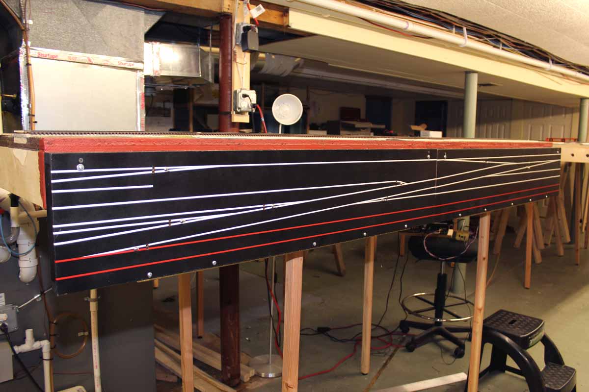
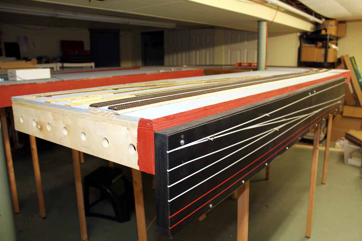
Control
Panels
I was asked why I was making “control panels” if I was using DCC. Simplicity! I
want the learning curve to run my layout to be about 3 seconds long. Once you
master the use of the NCE handles, controlling turnouts are just flipping a
toggle switch. All turnout controls are shown in their actual place on the
linear panel fascia. The panels are Masonite that hinges downward with auto pin
striping for the track diagram. They will have bi-color LEDs to help identify
the turnout route.
The 4’ long “bridge” section only has a crossover on it so it
has a smaller control panel. All DCC equipment is being mounted on a shelf on
this section. It is the perfect ½ way point for the power buss to go left and
right. The buss will terminate at the ½ way point on the other side. I am
installing snubbers to filter and correct the DCC signal in the buss at that
point.
With
any luck I will be running some trains on my layout by 10-17-11


Updated 11-4-20
All photos and content © Lanes Trains 2005-2023