|
|
Page
5 New
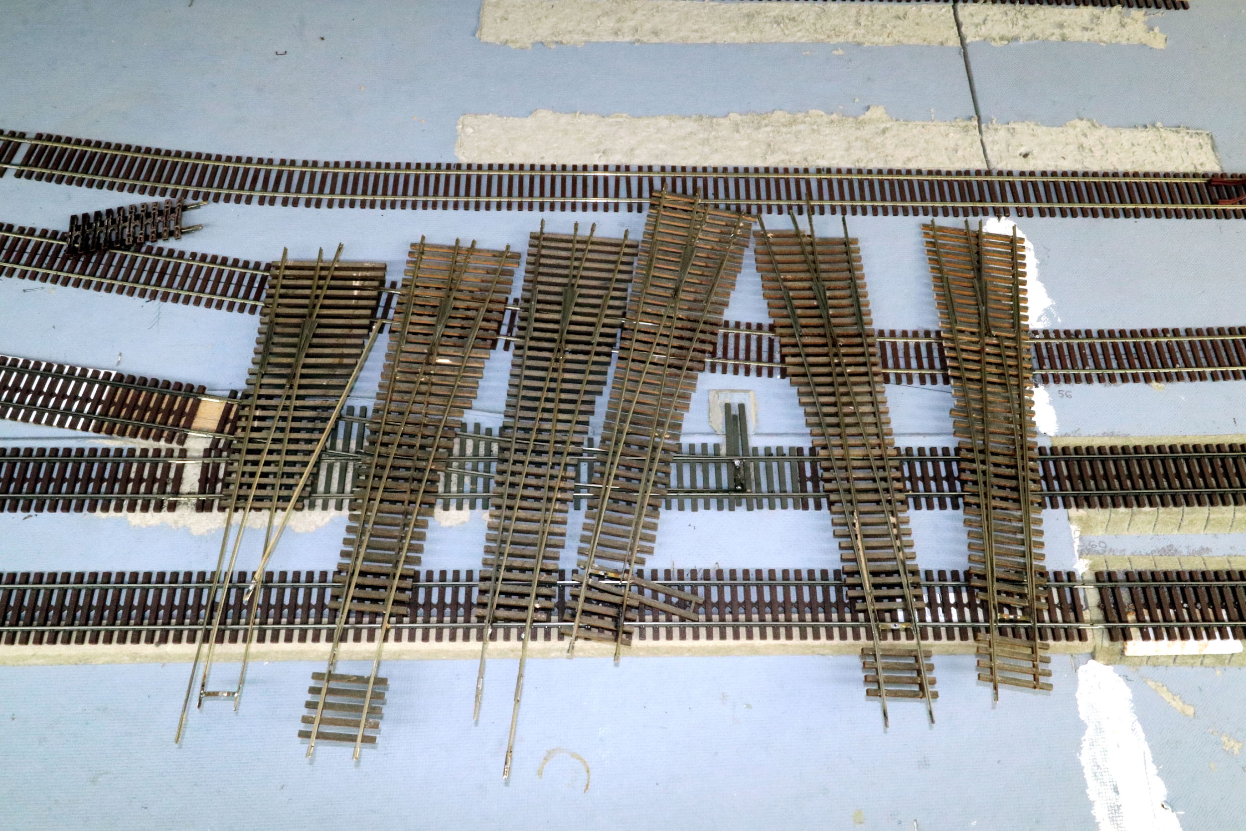
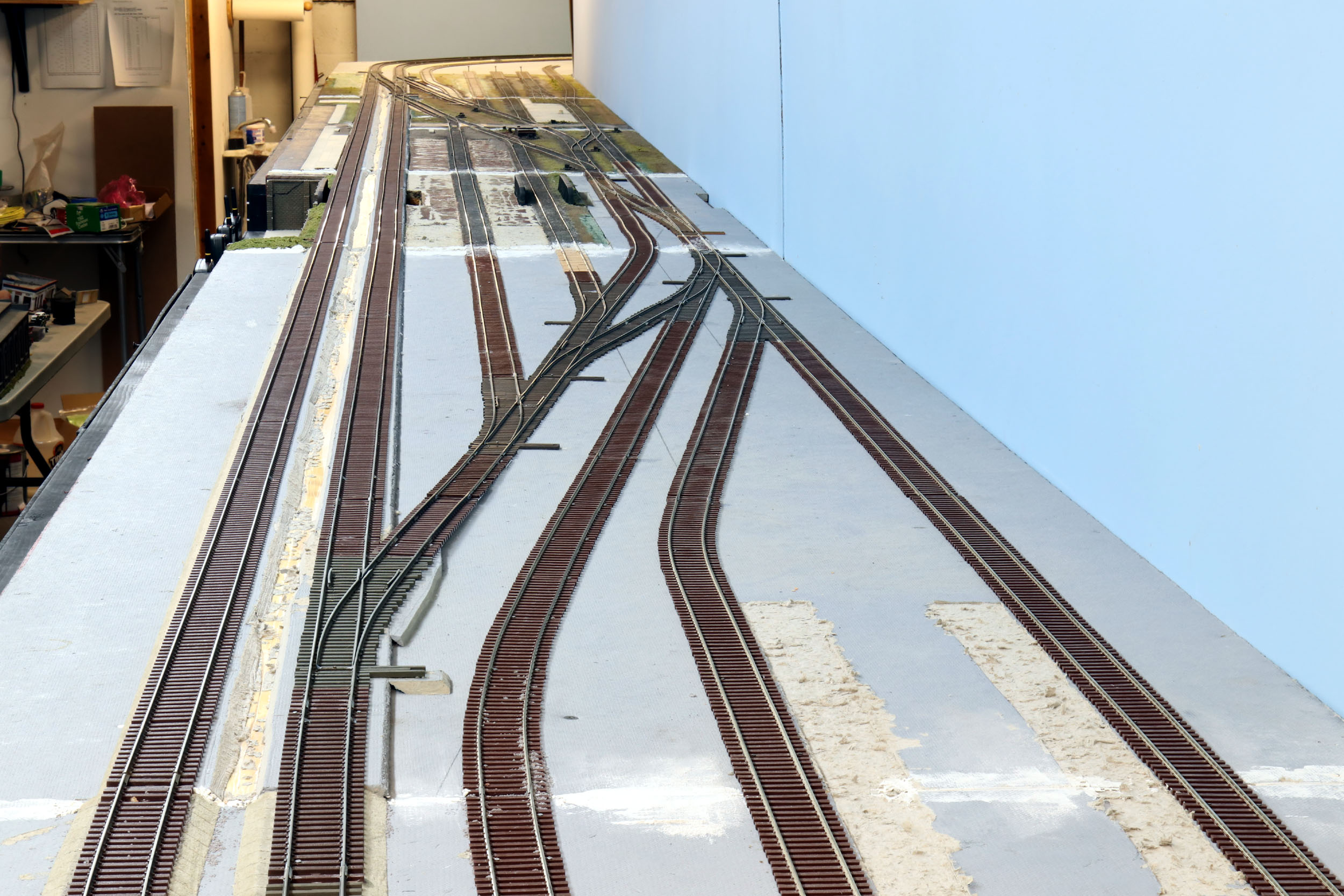
Replacement Yard Ladder Added
10-24-20 This is most of the original ladder that got replaced. 1
turnout is not fully shown at bottom center.
You can see a problem in the down ramp track. It hit ground
level then goes right into a turnout. It was a problem for many years.
|
|


This project has been a thought and in progress for a long time.
As mentioned on earlier My Layout pages this layout section was built as a
replacement for an original section with a track plan I did not like. The
turnouts used were left over from a previous module idea that never happened. A
combination of being in a bit of a rush to get them installed and the layout
running and 6 brand new turnouts that
were significantly out of gauge made them problematic from the beginning. I
spent over an hour each during installation getting them in better gauge but
they still caused derailments. This area is a key junction point for access
from the mainlines to the rest of the layout and ice
platform on the other side. It has to run well.
I bought individual turnouts from my friend John Wickham. John
has made all my turnouts, but I decided chopping his separate turnouts up to
cram them in place was not the way to go. The originals are all #6 turnouts but
some were cut really short to fit and complete the track plan within the 8’
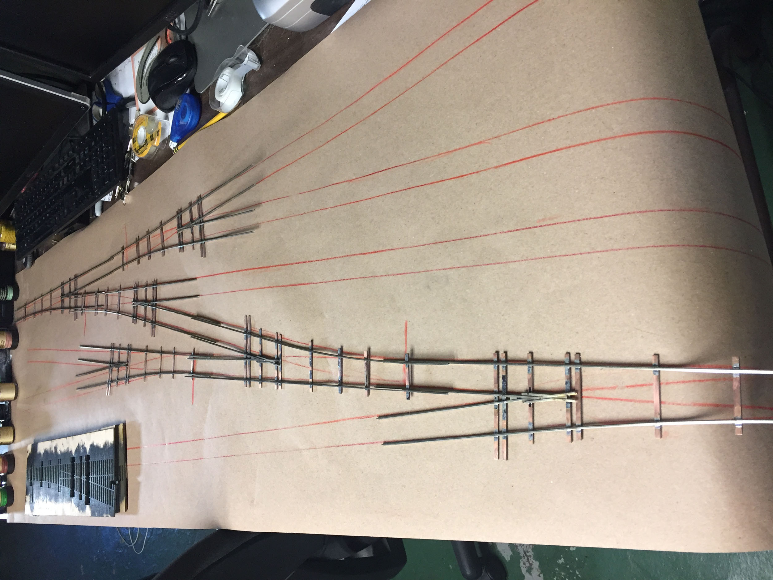
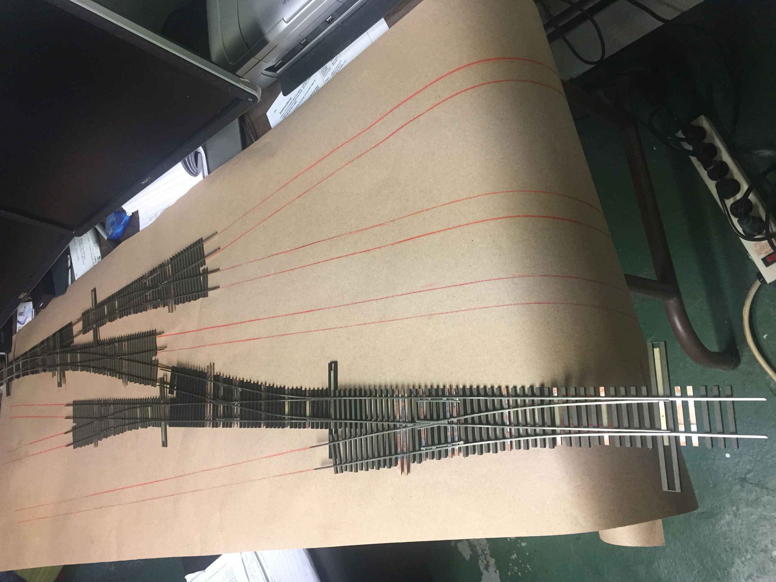
section. A new all custom built ladder was needed to drop right in place. John
came over and we did the rub down like he has before for making my curved
crossovers.
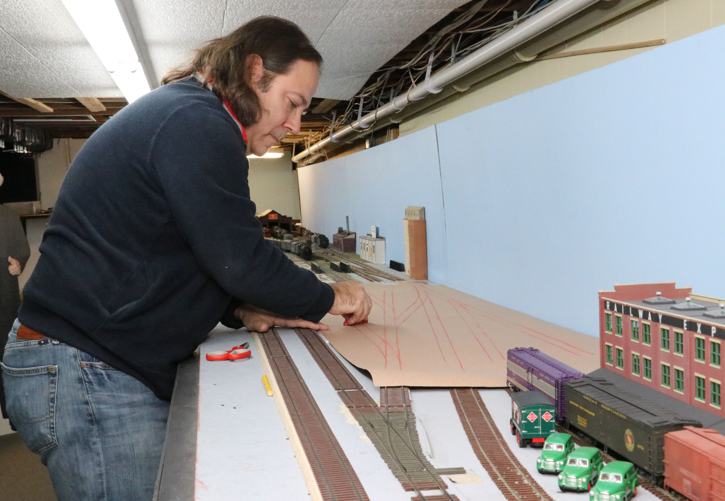
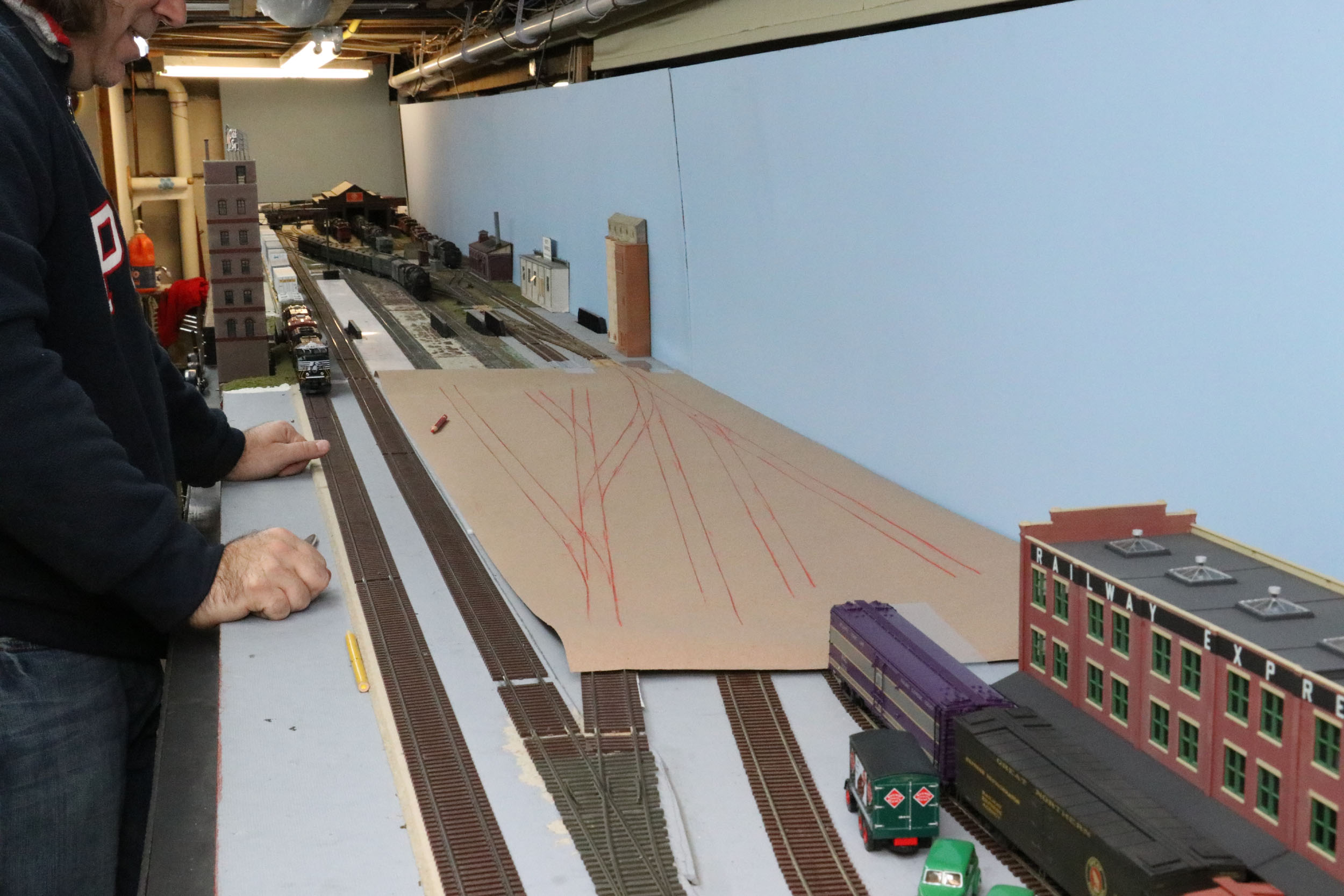
John is amazingly accurate in making turnouts from a paper rub
down of the track.
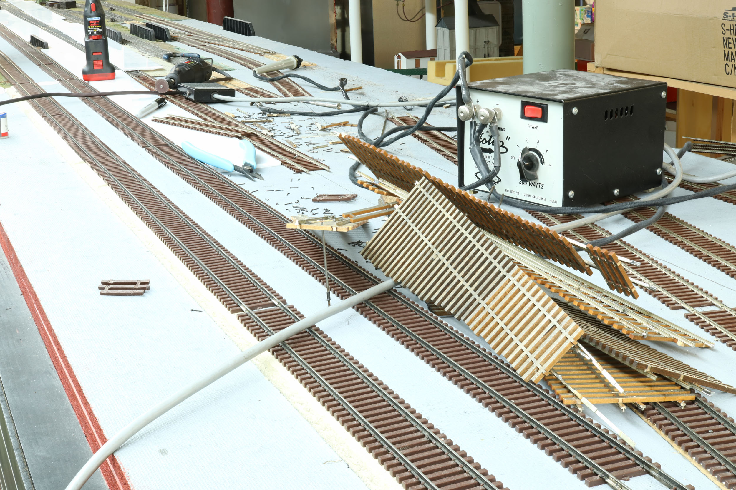
Demolition
Day 10-23-20
I used 1 of my 2 PBL Hoptip 300 watt
resistance soldering units for layout and track work. The
old turnouts did not survive removal in spite of a reasonable effort made to
save them. It is just rail glued to wood ties. S Scale track does not recycle
well.
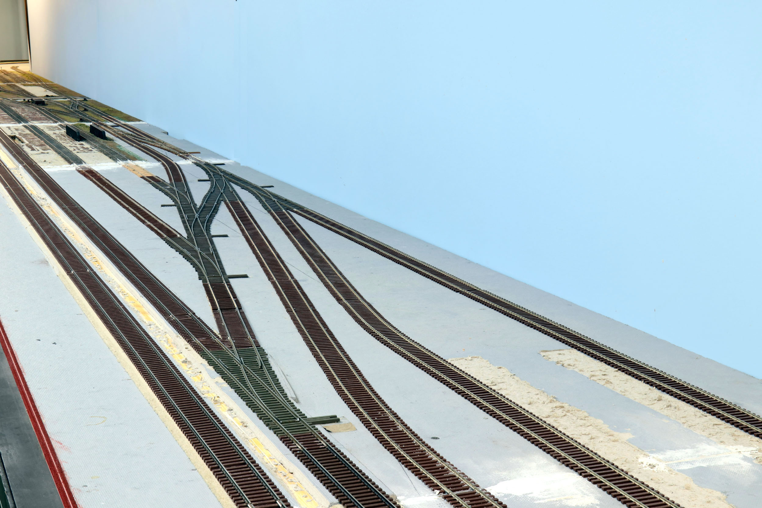
New
Ladder Installed 10-26-20
Installation was almost 3 days of work to make sure everything
lined up correctly. Not 1 piece of rail was cut. John could not have made the
ladder any better if he built it here in place. There is no single change to
the layout that has made such a massive positive change as this new ladder. All
new ballasting and scenery was waiting for this installation to happen.
Other
Trackwork
There are other areas of track that might have been rushed and
not done well. It turned out to be a large number of dips, and in some cases
track I never spiked down. They have been a derailment problem for years. It is
time to fix them and make the layout run better.
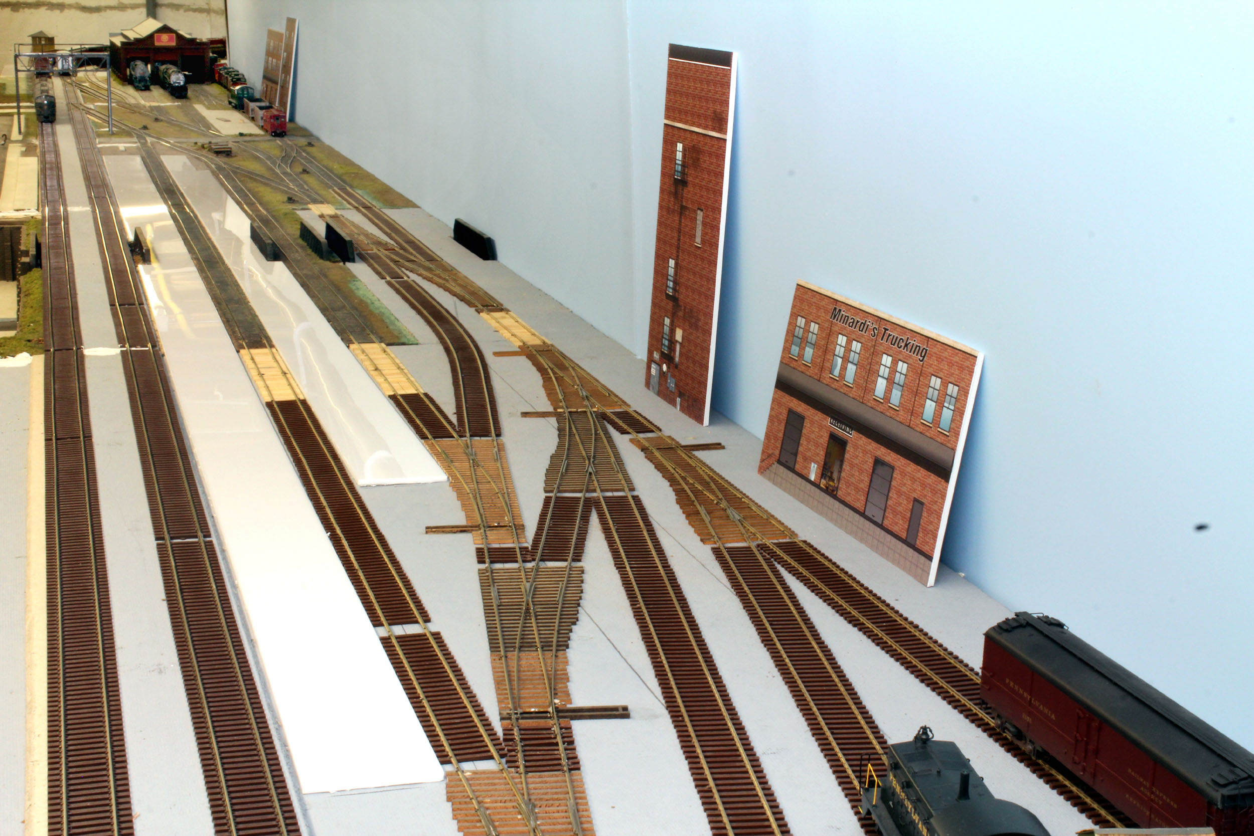
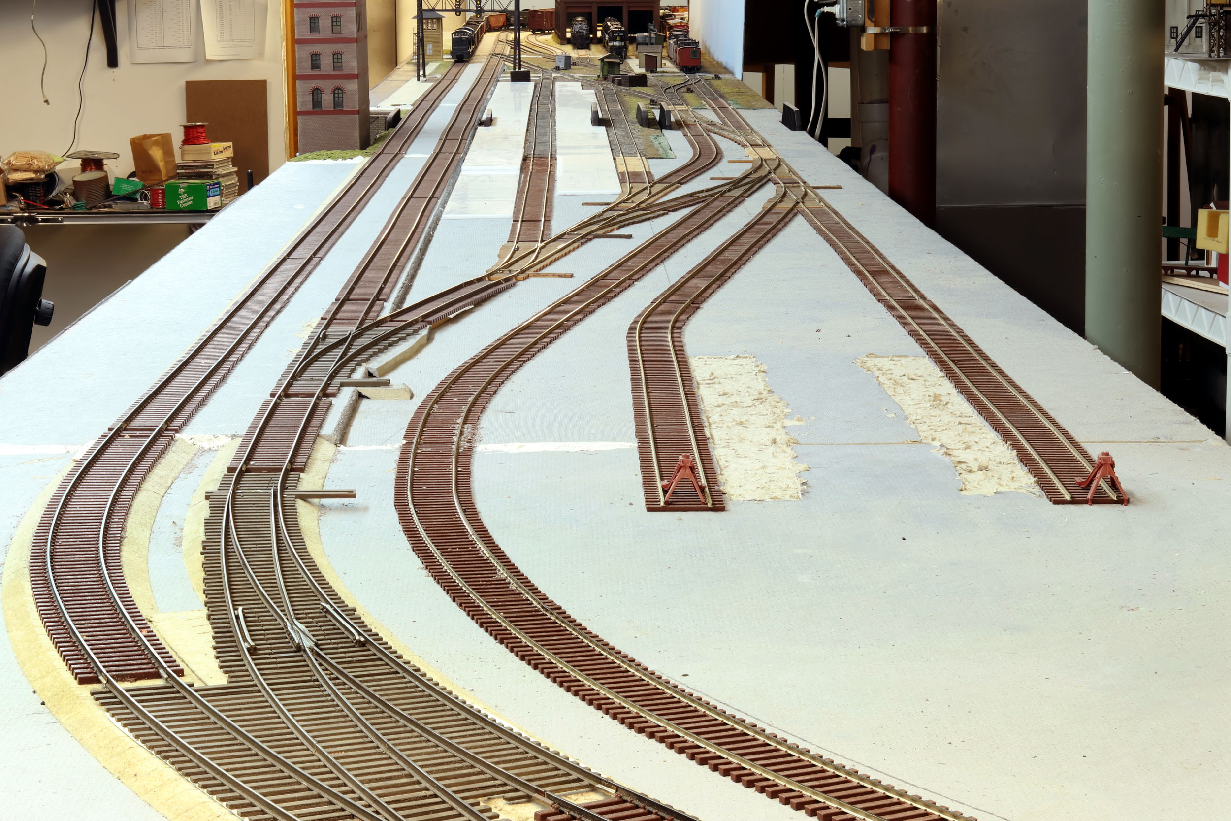
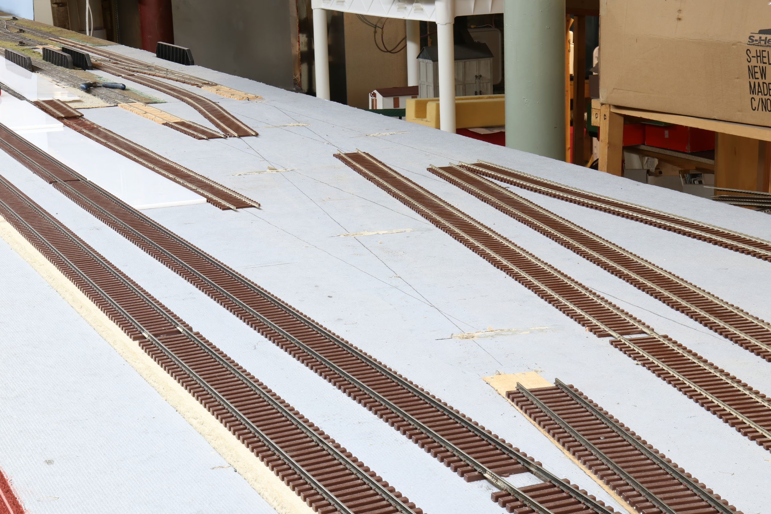
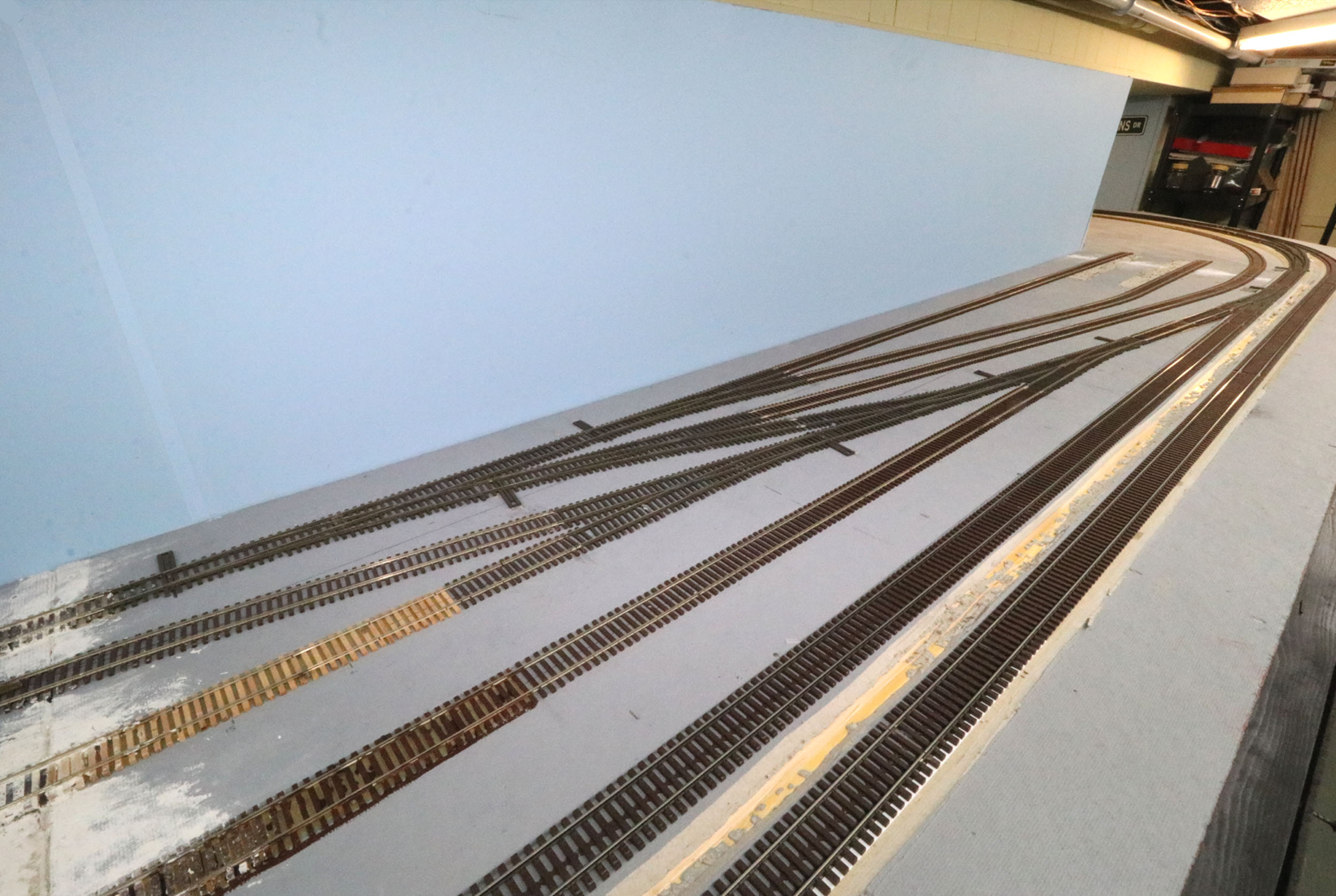
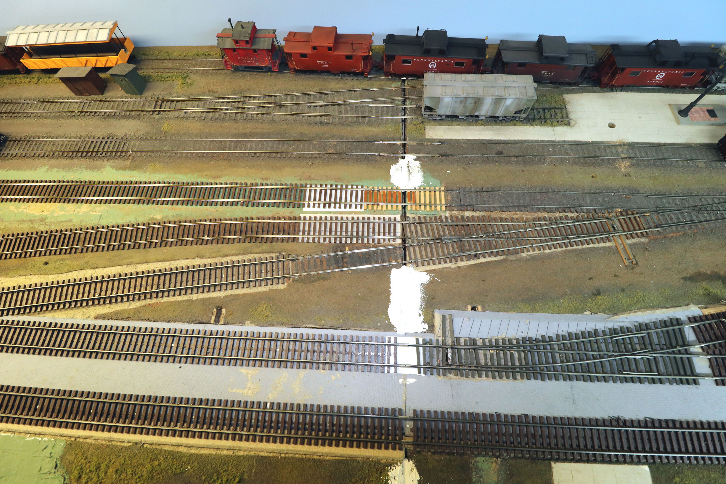
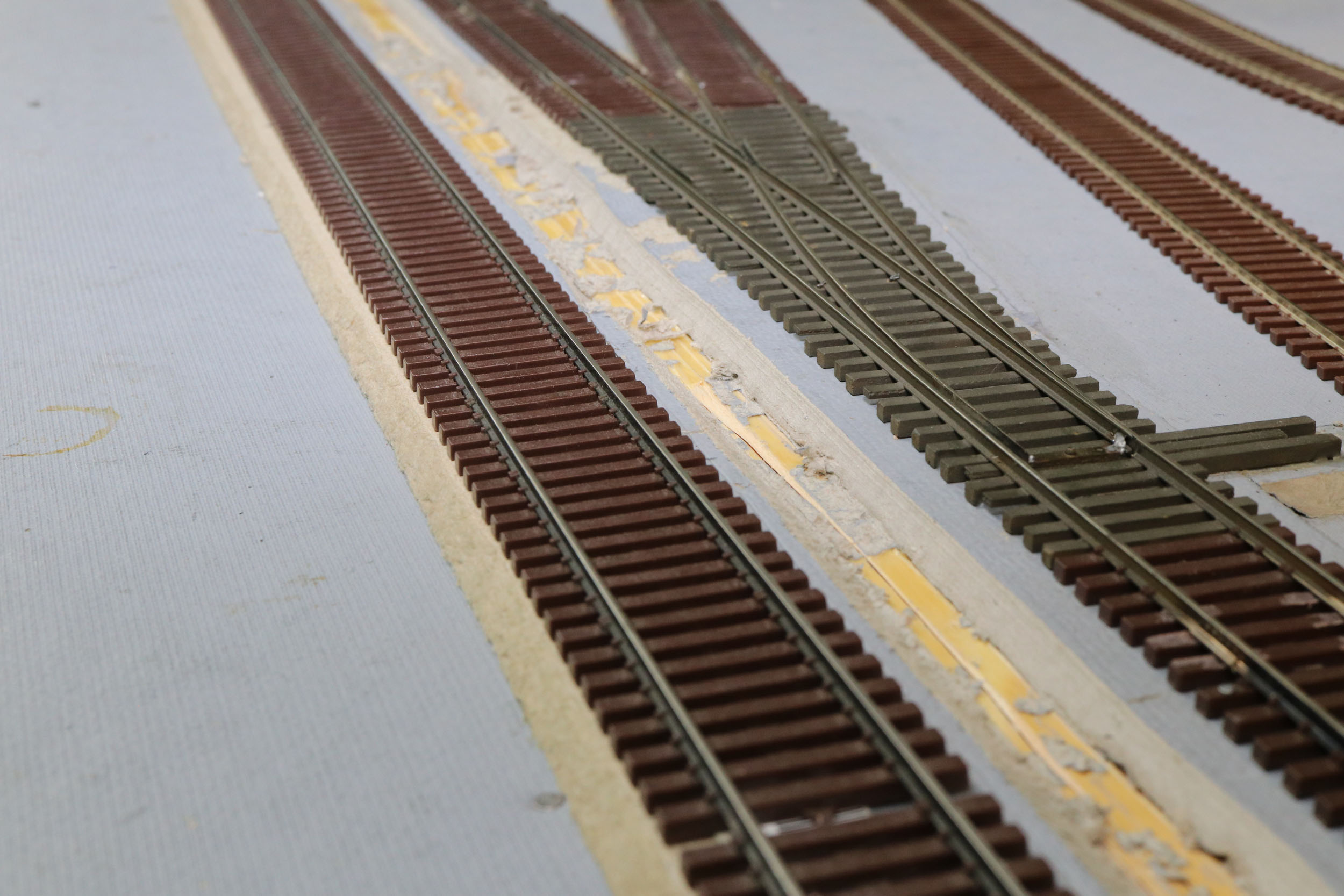
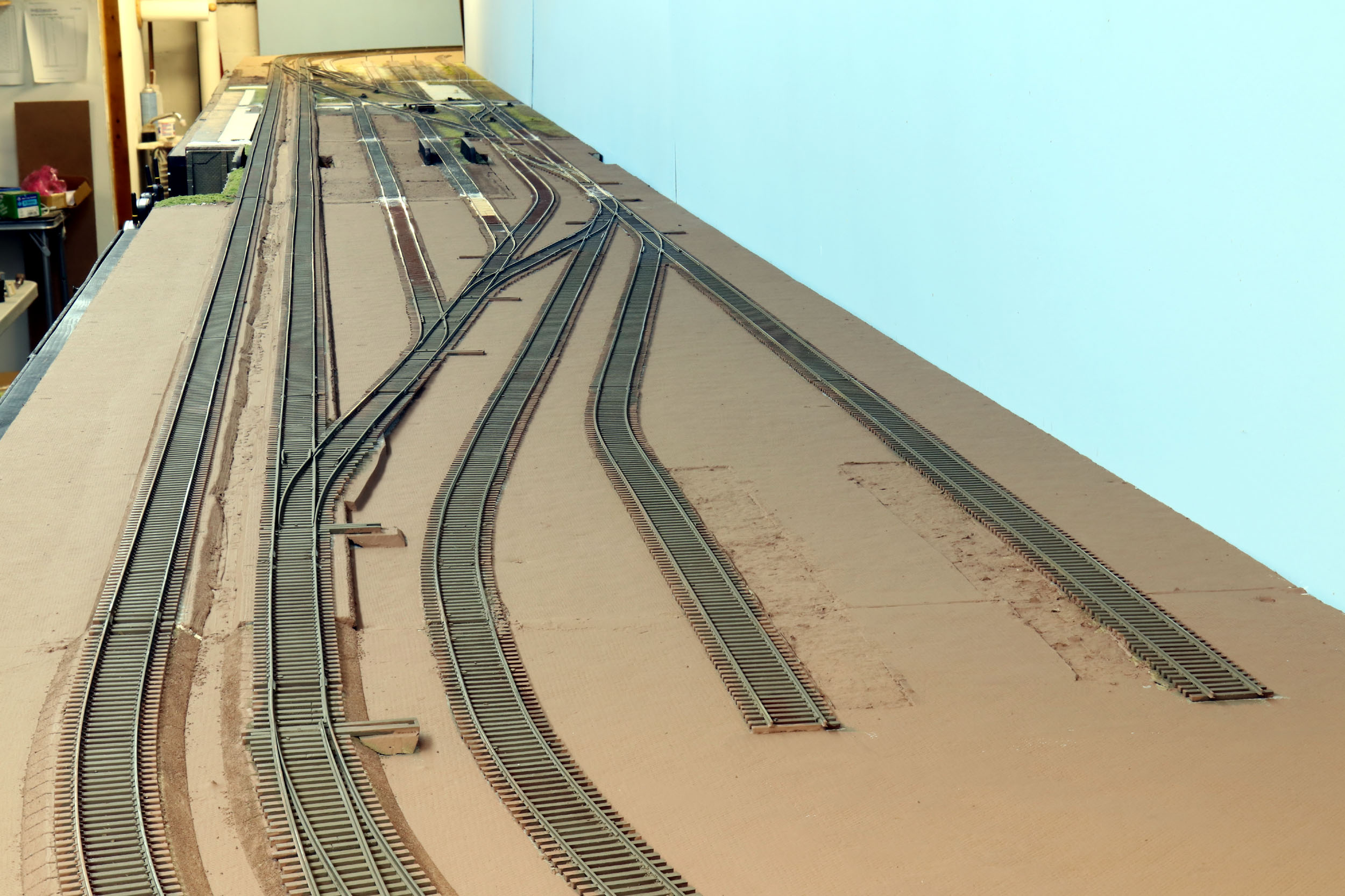
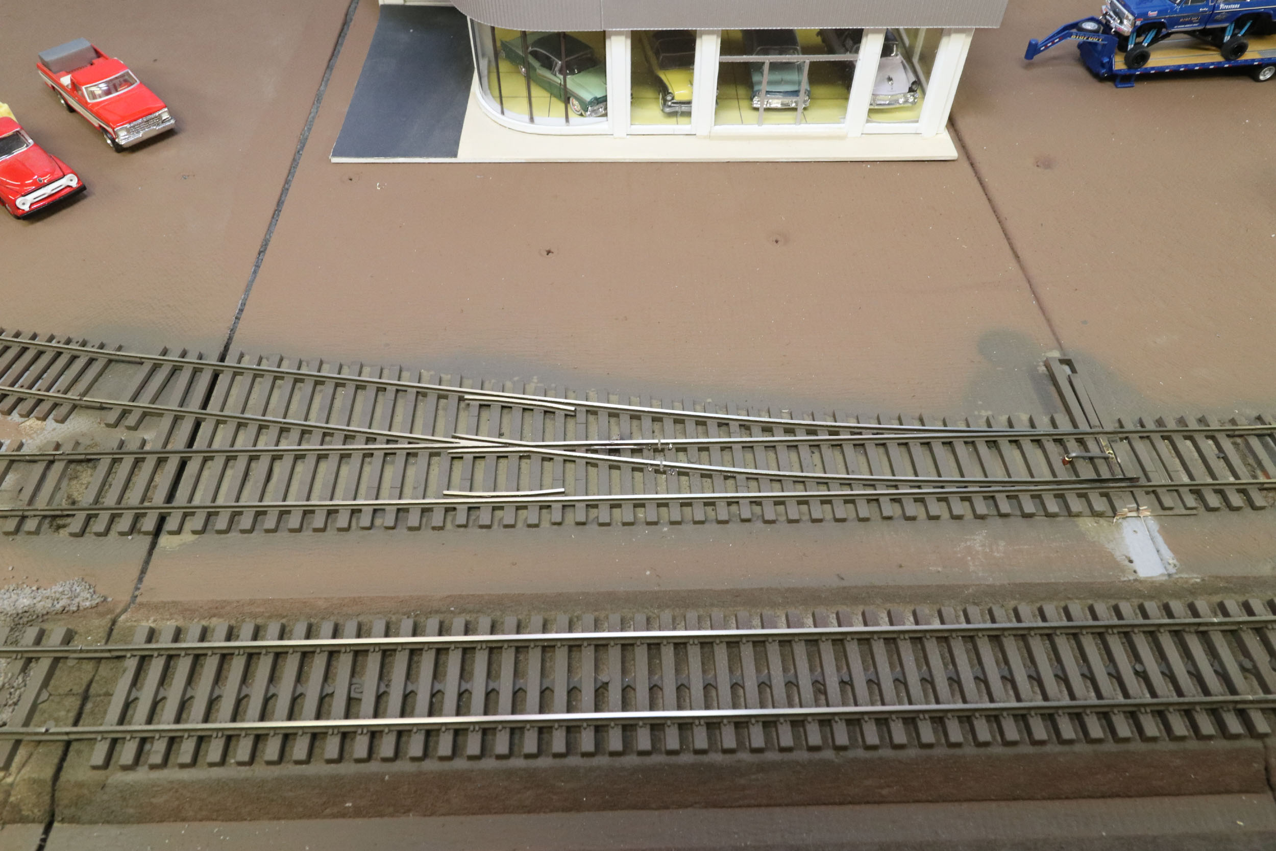
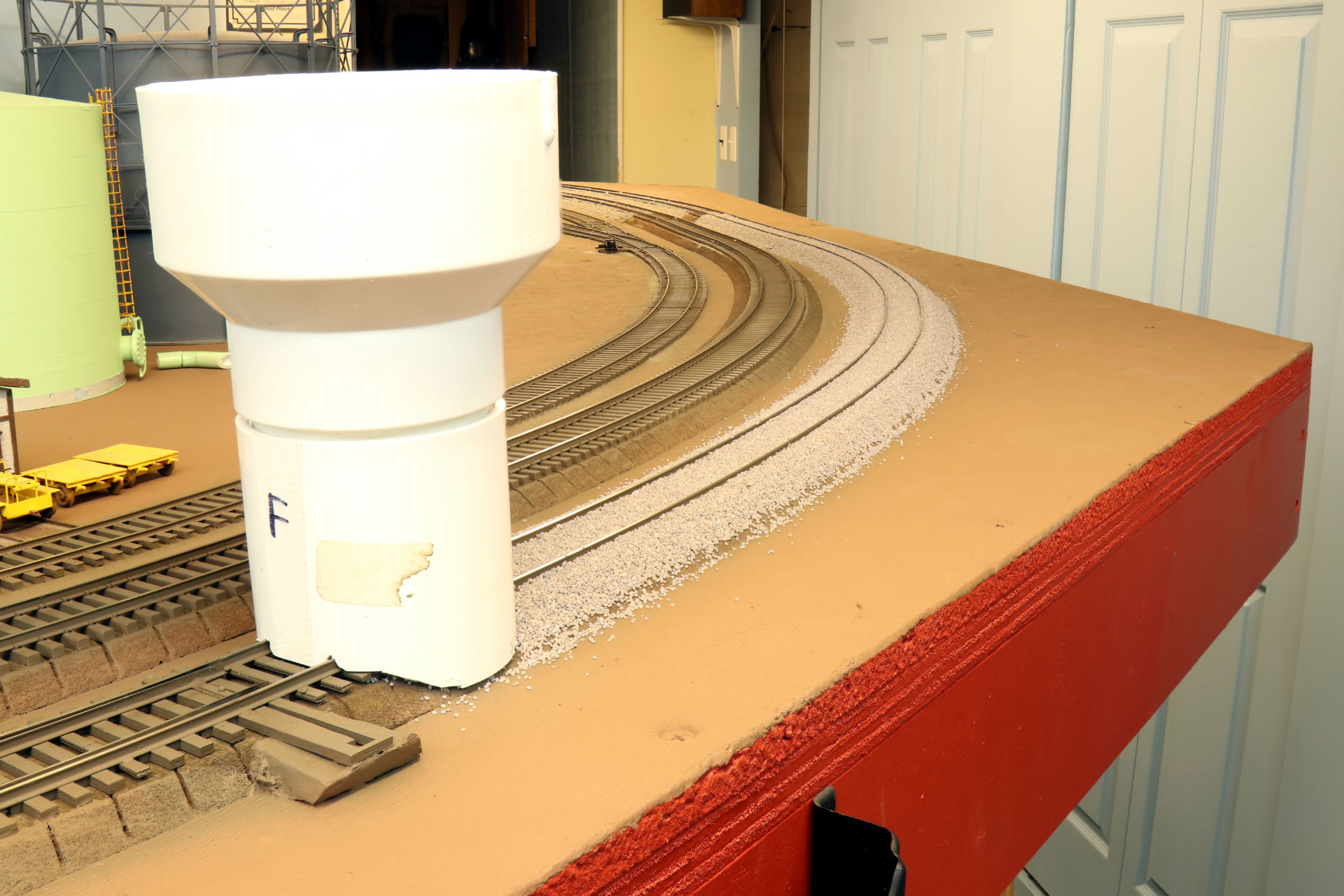
The mainlines
are code 137 track on ¼” high roadbed. The rest of the layout is code 100 flat
on the deck. I call these “downramps”. This is
actually the right side beginning of the new ladder above. There is a lot going
on here in 14” of track. The track is dropping ¼” and changing from code 137 to
code 100. It is a construction wood shim for the ramp itself. This section used
to from change code 137 track to code 100 at the beginning of a turnout – not a
good idea. I made a new track section making the rail change in the middle of
the ramp. Going right into a turnout once on the deck was not a great idea but
I had to do it to get the rest of the track plan to fit in an 8’ layout
section.
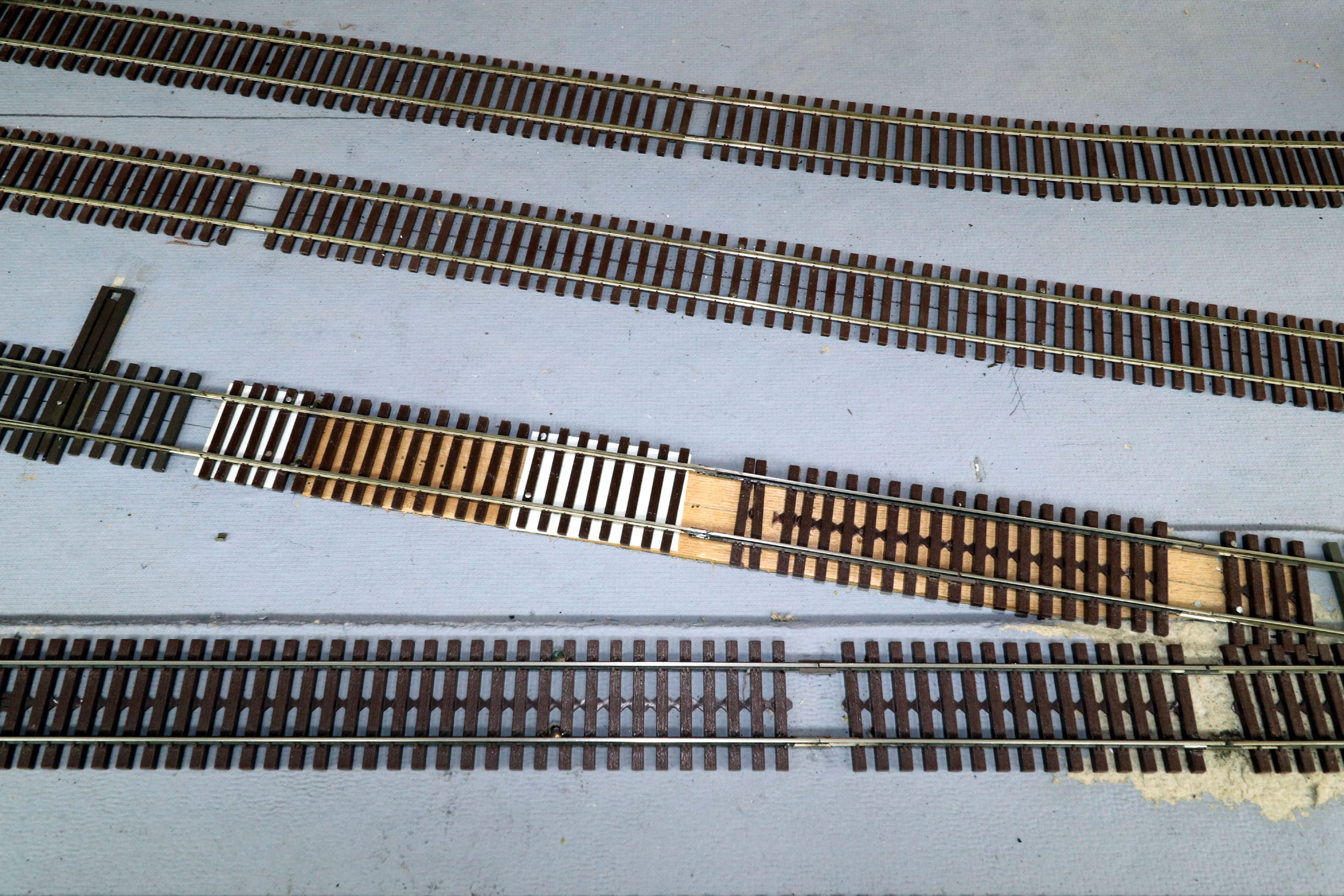
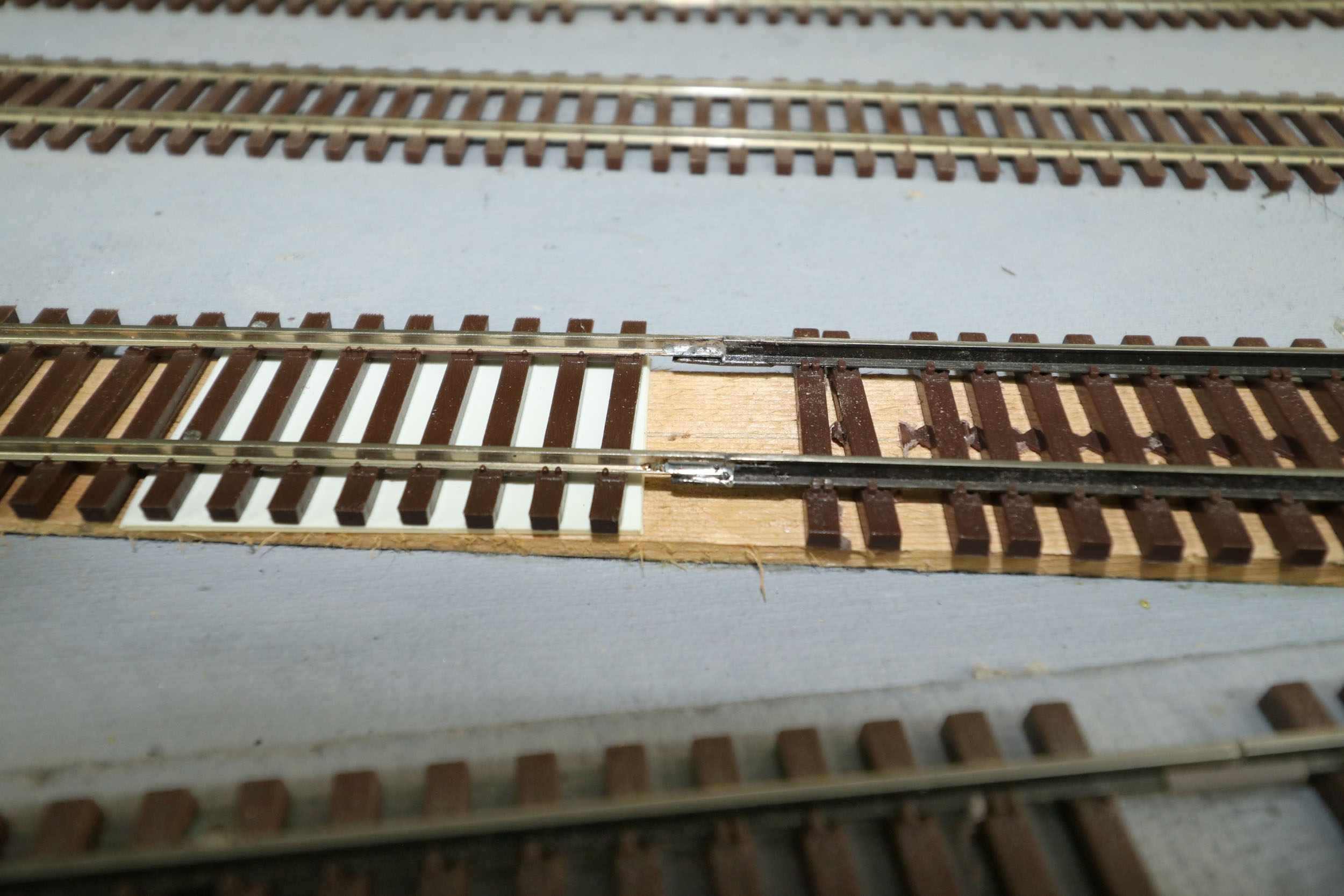
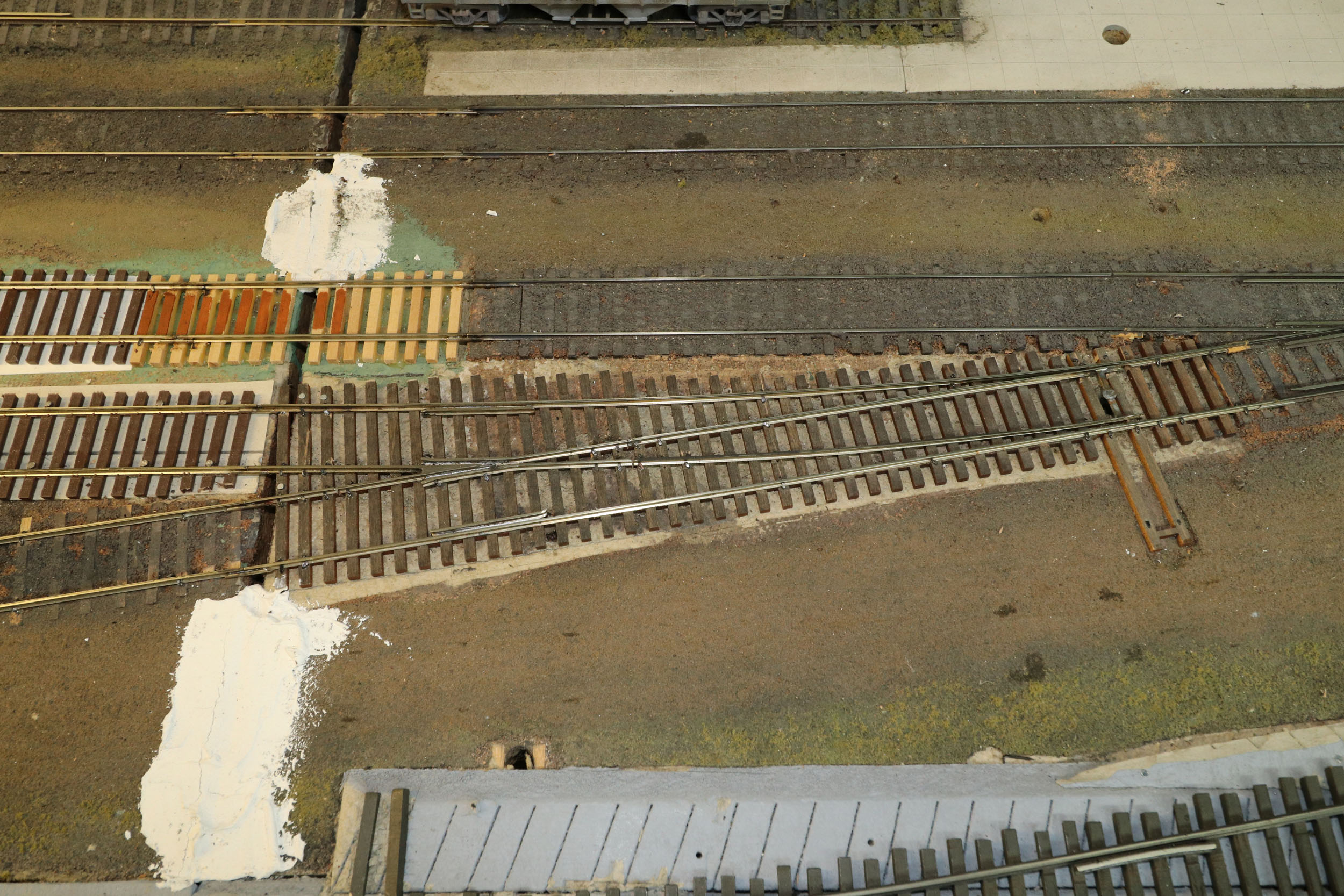
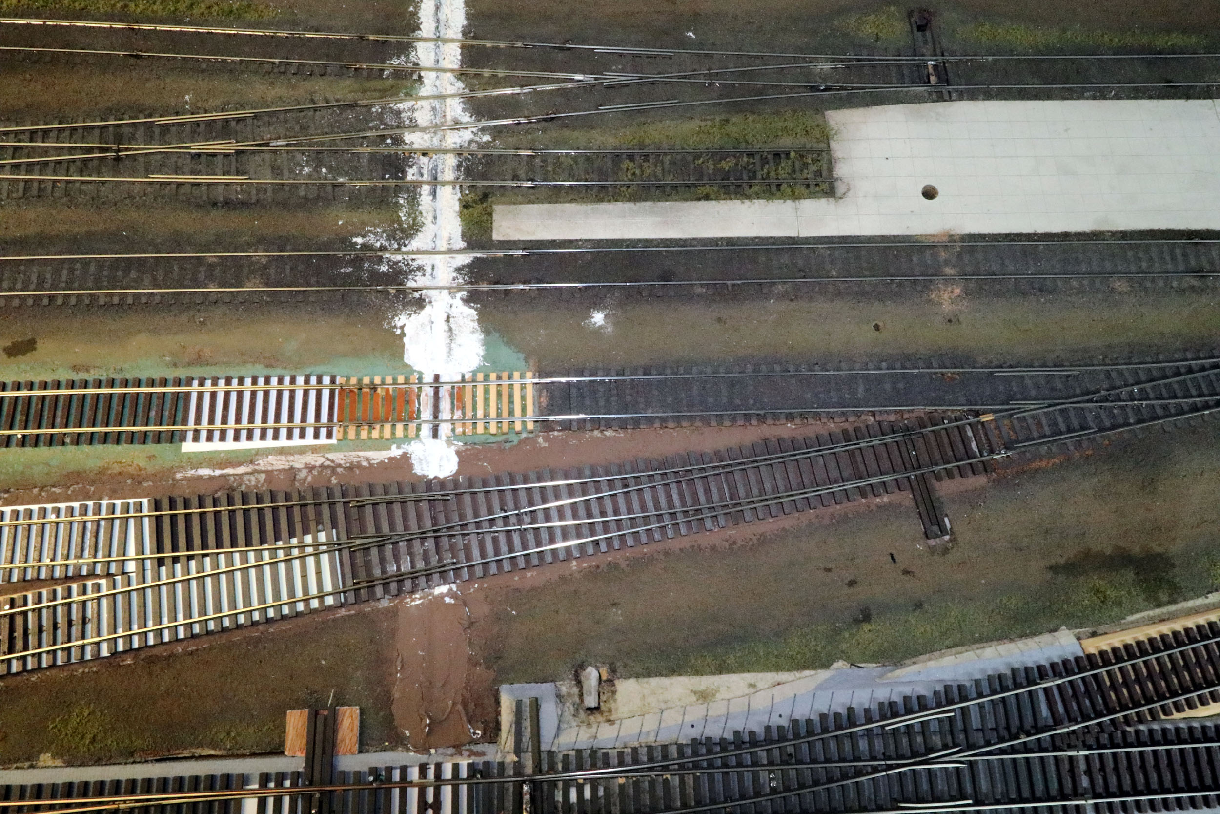
Code 100 rail fits into S Helper Service code 137 tie strip. I had wood ties and bridge rails here as my old module building ways. I took out the wood ties. The turnout at left had issues so I slide the SHS tie strip onto the left turnout and continued to make the joiner section connect to the turnout at right.
With the yard ladder replaced now this was the worst turnout
left on the layout. It was cut very short. I tried too hard to cram a turnout
in and not cross a benchwork section joint, also a module building requirement.
I had to get over ending all track at benchwork section joints since these are
not modules. As time went on I have continued track over section joints but
never put a turnout in place. 9 years after the layout first ran I am now about
it running well. Also note the adjacent track going to the engine house was
very close. This was the layout pinch point. When a turnout was as problematic
as this one was ripping it out with pieces really flying was big fun. I thought
if the layout ever had to be moved add steel angles to the bottom of the frames
and move as 1) 12’ long piece. It would be a bit cumbersome but still better
than moving with a chainsaw like many other layouts.
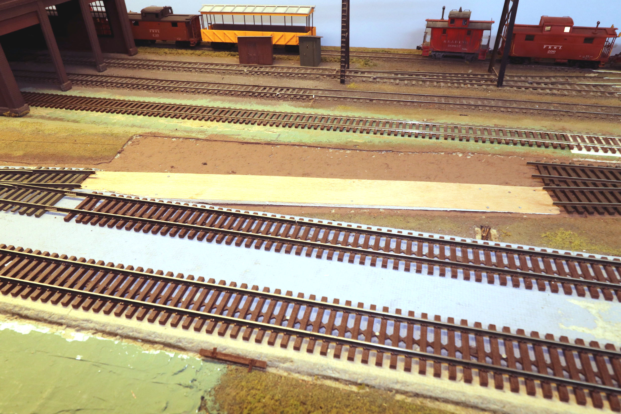
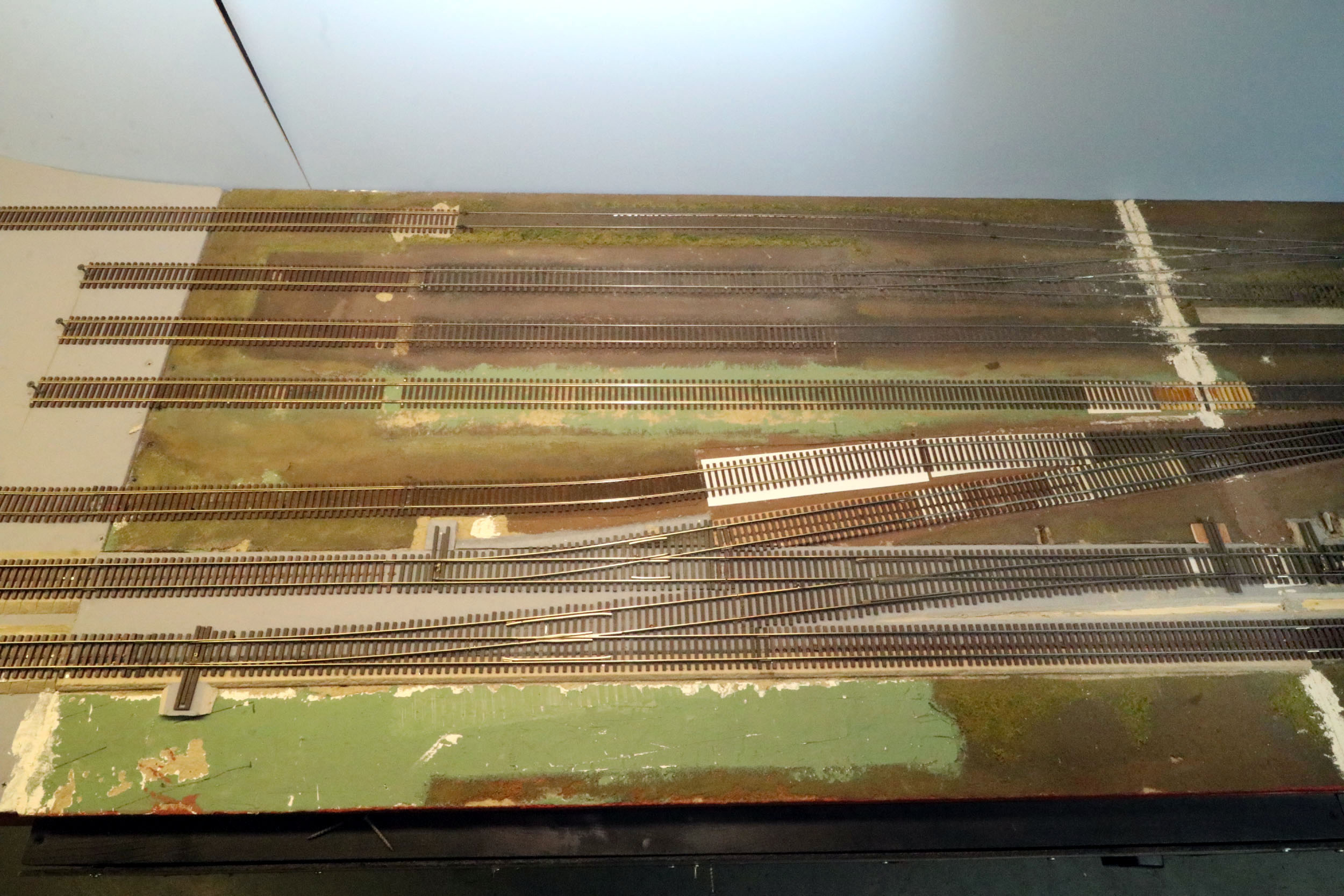
I made a new longer down ramp. I was going to move the turnout
about 3”to the left but I changed from a #6 to a #8 turnout instead. This made
for a straighter line to the yard lead at left and more space apart from the
engine house track. That is a whole bunch of wins all with just 1 new turnout.
This track is now significantly better than it has been for years.
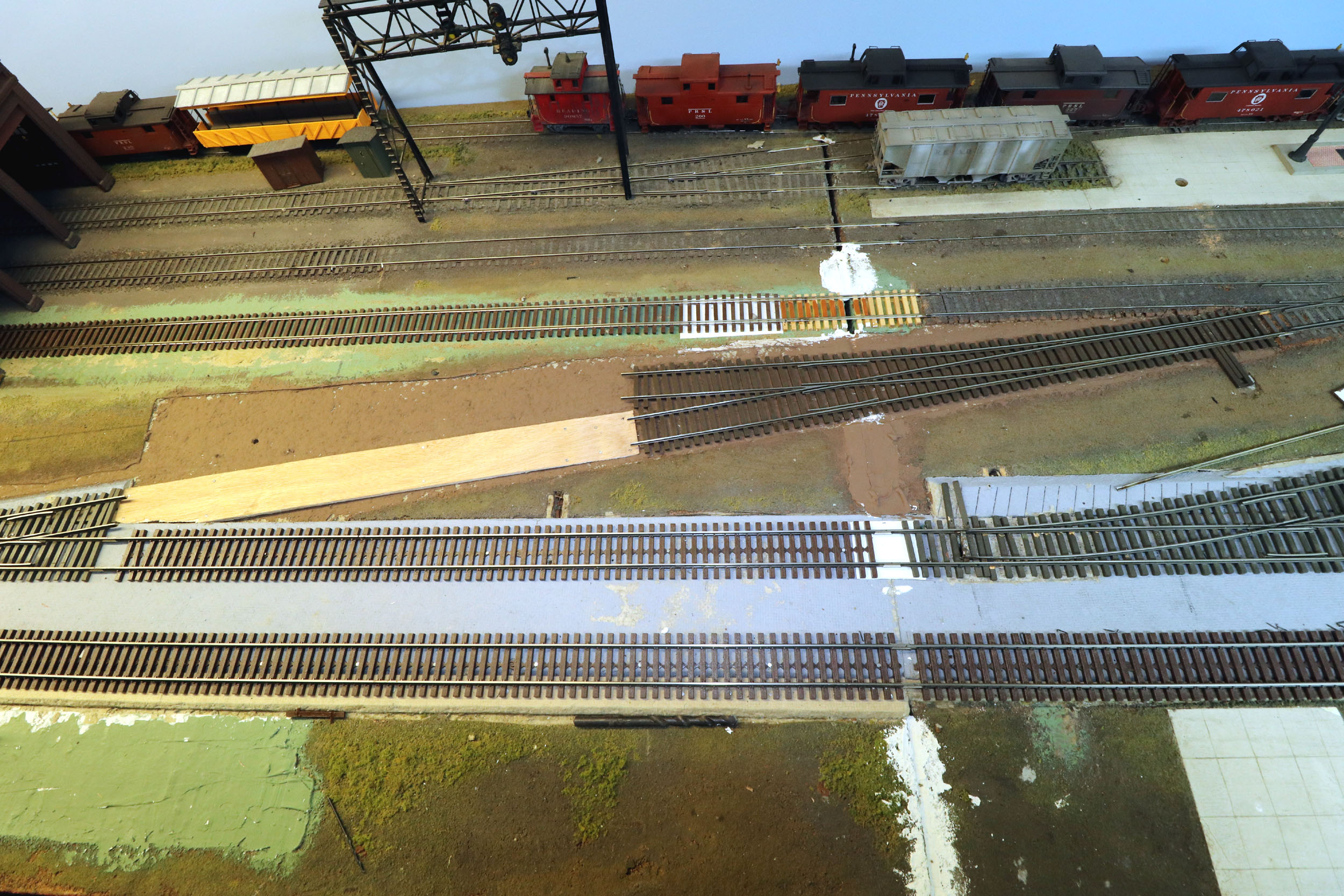
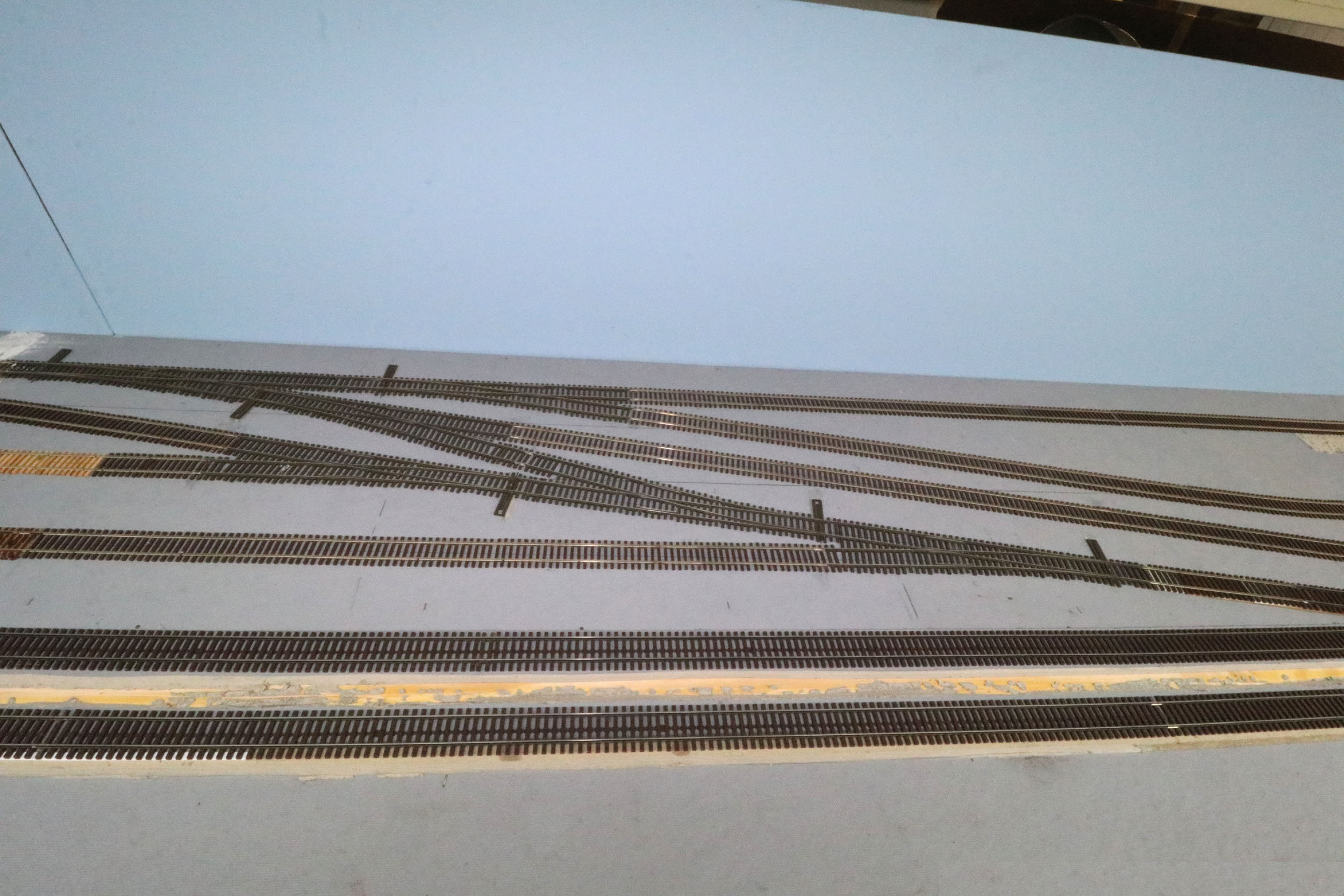
New
Crossover 10-27-20
I have had the idea and turnouts for this 5th and
final crossover for a few years. It is a #10 that is 45 inches long! This is to
add direct access to the passenger station. The curved crossover is about 4
feet to the left and can do the same thing. All my other crossovers alternate
in direction. This is the same outside main to inside. I get that this is a #10
turnouts right in between to 2) #6 turnouts. The #6 should have been at least a #8 but there was no room. Further I just replaced
what was previously there.
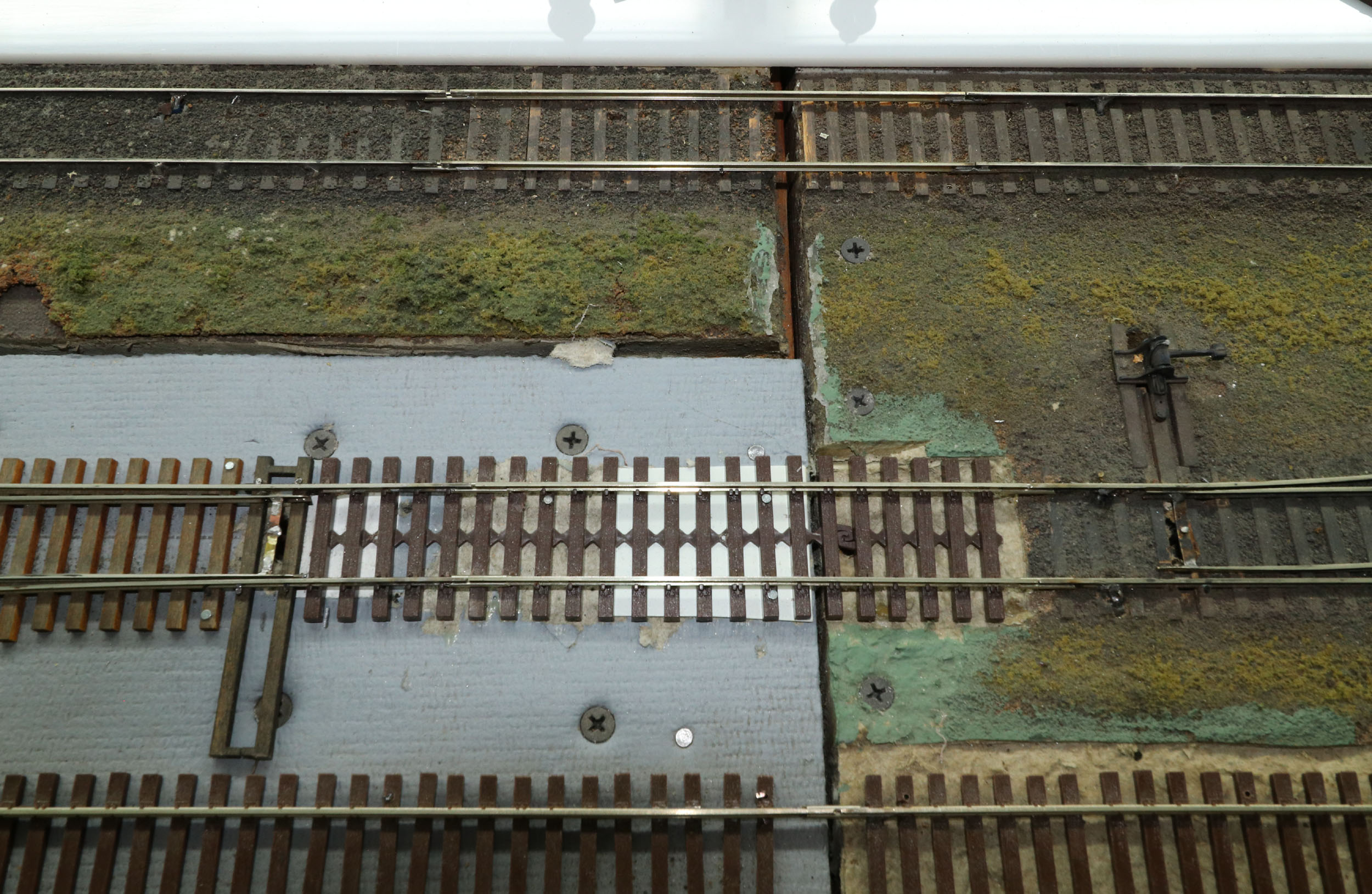
As I have previously mentioned the purpose of using the code 137 track was to show grade separation and definition of the mainlines. This was all perfectly good ballasted code 100 track in this place but was flat on the deck that I removed because I wanted elevated mainlines. I carved a “V” out of the ¼” Homasote to give the ballast a roadbed profile.
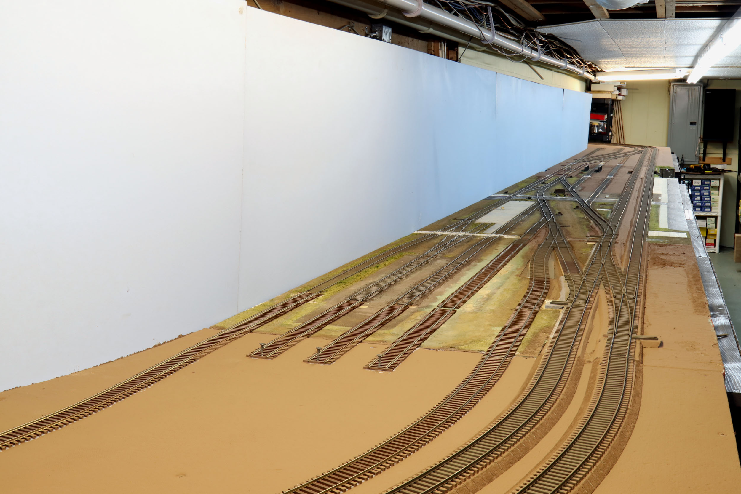
Goodbye
Blue
Some people have asked if my layout was blue foam board, or why
it is a “Colonial Blue” color. All Homasote has to be sealed before using it to
control humidity swelling. I did not want to buy paint for sealing the
Homasote. When we got our house we painted all the rooms. There were various
partial cans of paint leftover. I got them all and mixed in a 5 gallon bucket.
The blue is what it came out to be.
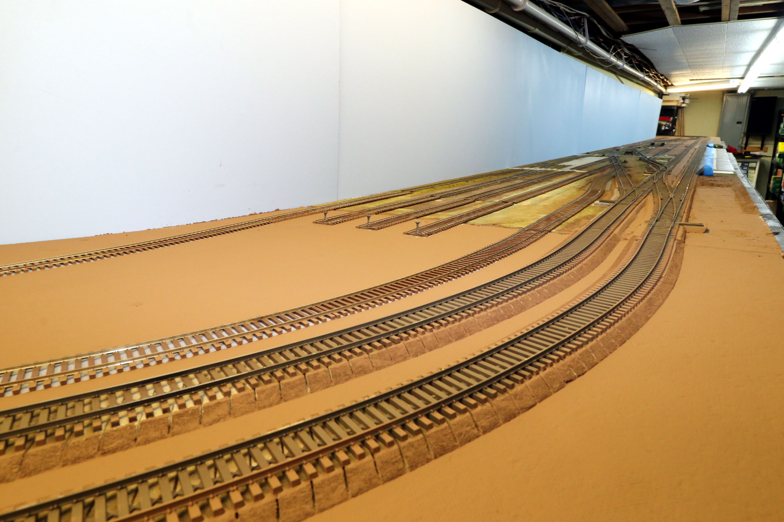
Hello
Brown
A few areas still need painting but what was once blue is mostly
brown now. The improvement is just massive. This is the very beginning of
scenery!
Added
11-11-20
The amount of work that has been done to the layout recently can
only be compared to the first construction. It was 3 weeks of doing nothing
else for 10+ hours a day. All of this work was needed to get the track in good
condition and prepare for the beginning of scenery. I also had to make the
decision that the track plan was DONE, which I finally think it is. It was plan
as I went along construction to this point.
More
Power
DCC
To this point the layout has been 3 power regions total, 1 each
for the mainlines which are about 100 running feet, and the code 100 everything
else that is possibly 300 to 400 feet. There could have been 15 locos sitting
in the code 100 track drawing power for the sound units etc. I have seen trains
pick up speed when crossing to a mainline because of no other locos in that
power region. Finding a short in the code 100 region was extremely difficult.
The entire track was live or dead at the same time.
More than once I went around and took all the trains off the track hoping to
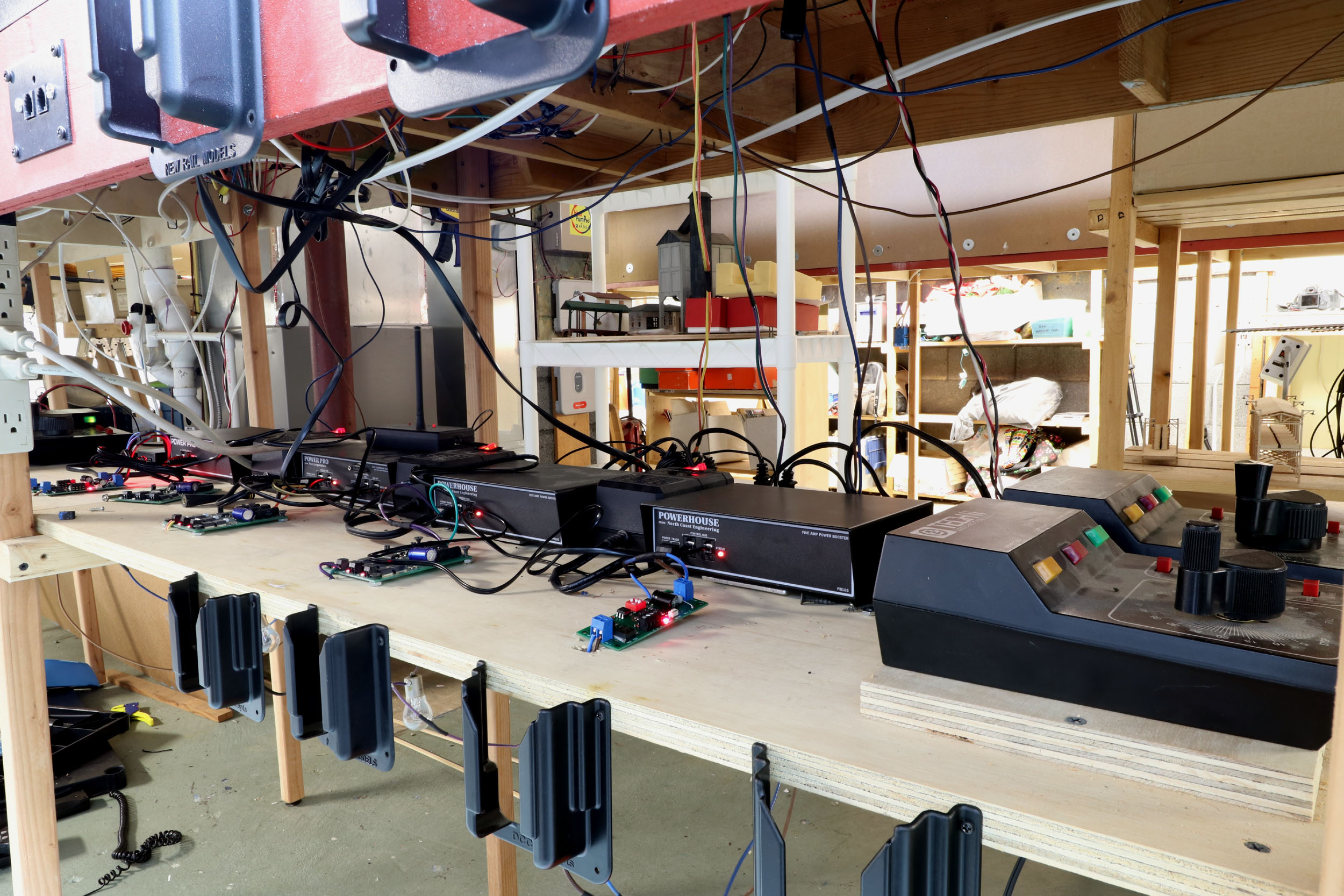
find the short. I have long wanted to
add blocks and more circuit breakers. The rather easy way that finally came to
me was divide the code 100 region up into about thirds by isolating 24 feet of
the layout and extending a new power buss wire to the left and right about 15
feet each. I then picked up the original power buss at that point. I added
another 5 amp PB5 booster and 2 EB1 circuit breakers. This made 2 new power regions
from that point to the snubbers at the “end of the
line”. It was scary simple really especially with my double terminal blocks and
jumpers at every layout section joint leftover from my module building days.
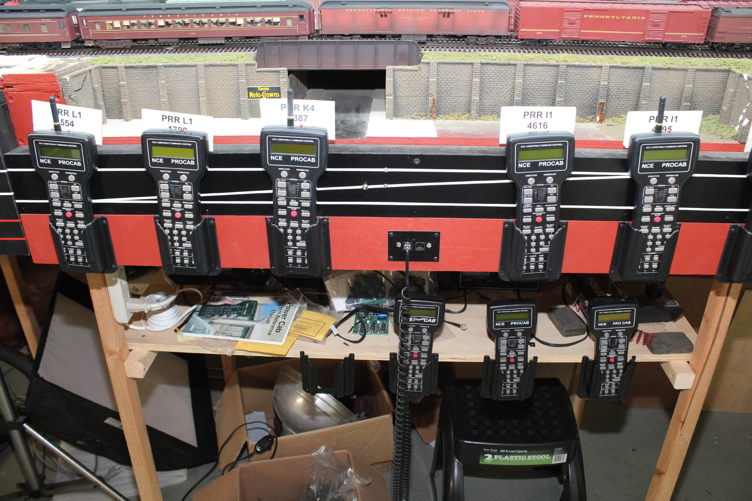
I have mostly all wireless handles. The NCE system has been
truly bulletproof for 15 years. I have never dropped a signal. They control response
has been equal to wired handles at all times. There is only so much room for
locos on the layout at one time so I made cardboard tags for each and use 1
handle per loco. They are attached with Velcro.
Control
Panels
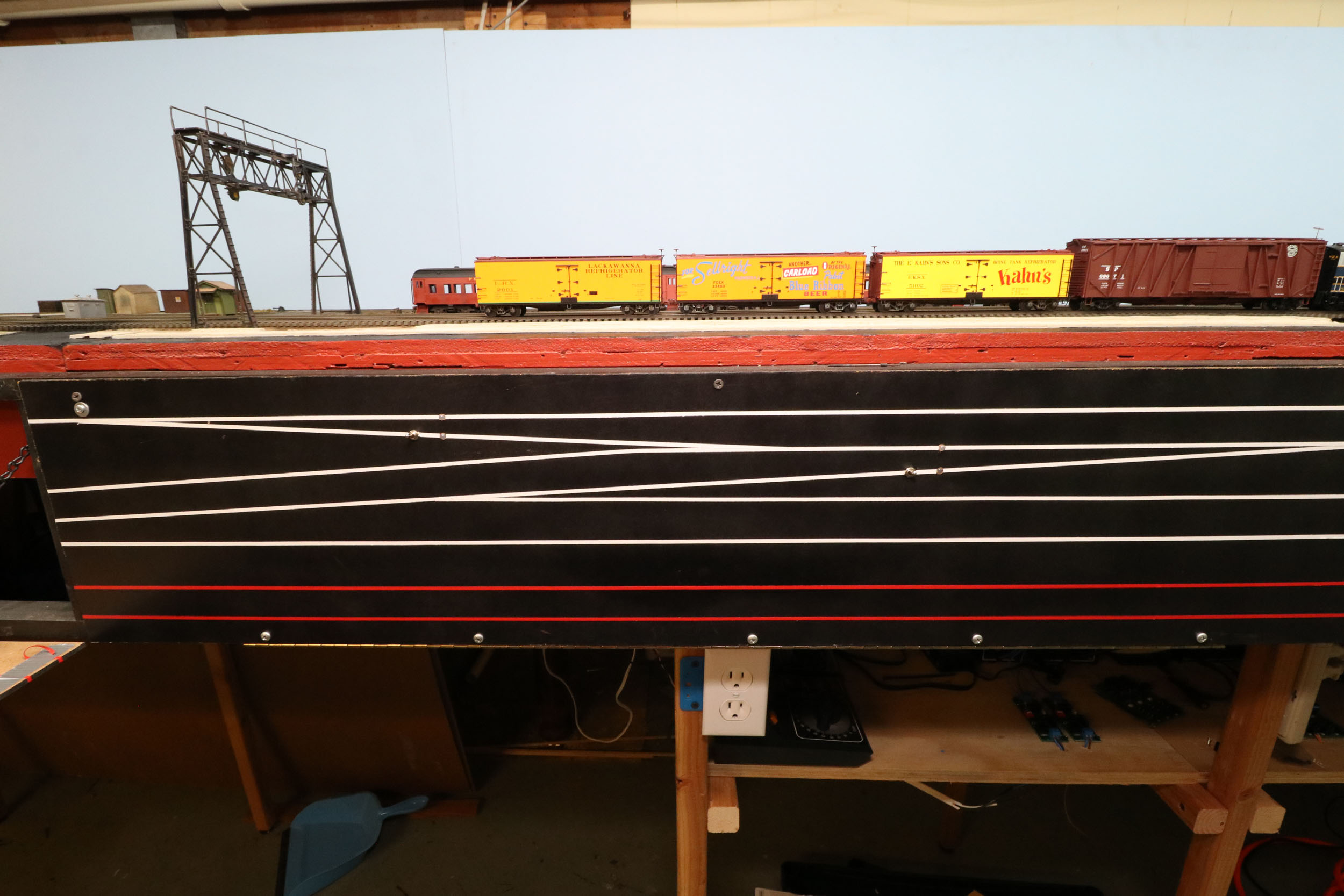
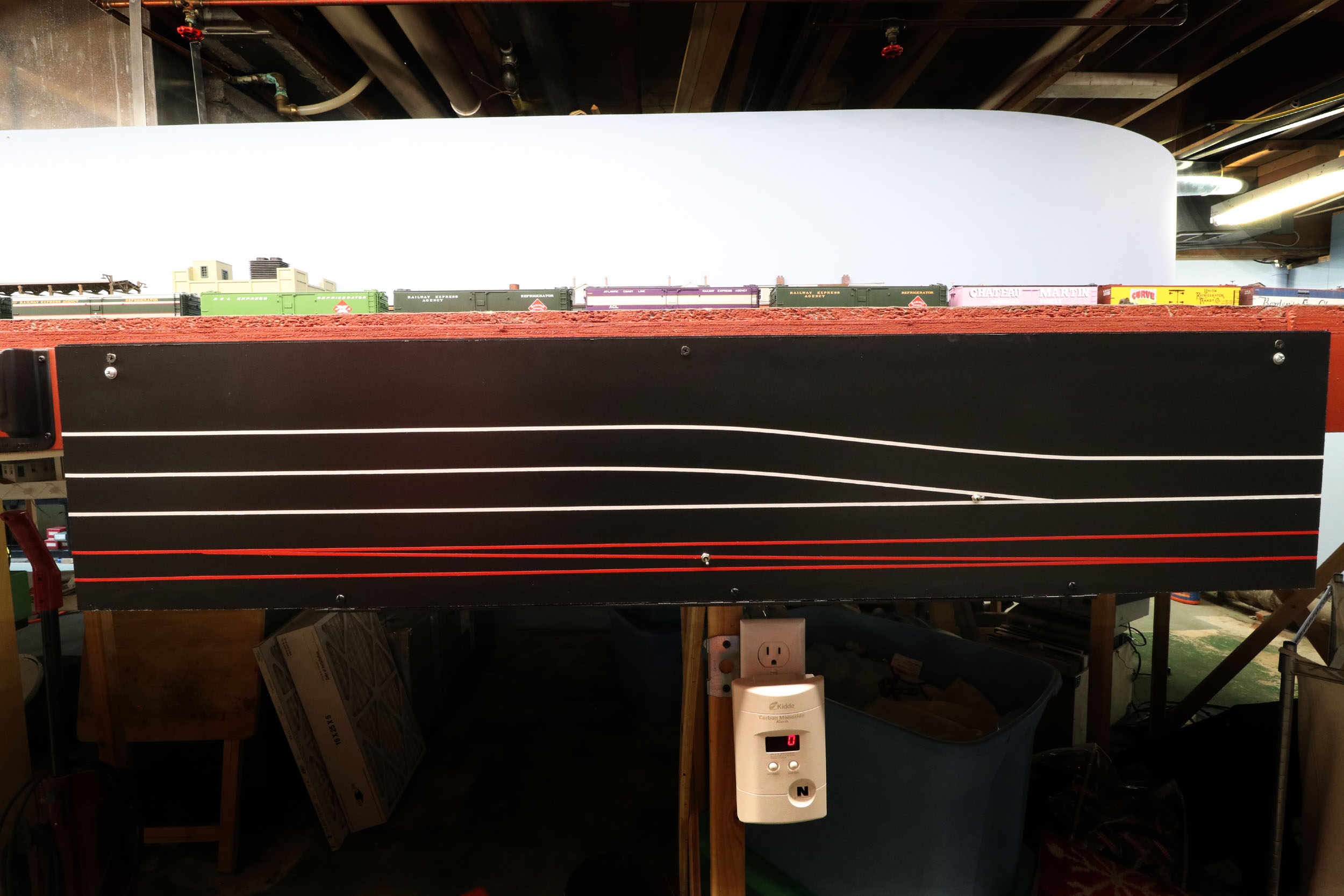
This is an original control panel in use for many years now. Red
lines are for the main line. White lines are the “code 100” track. Note the
bi-color LEDS showing route. The red wires also get used to power the LEDS. The
aluminum bar is for wire control. This is my version of a solder terminal strip
to save running back to the 3 power buss wires under the layout.
New
Control Panels
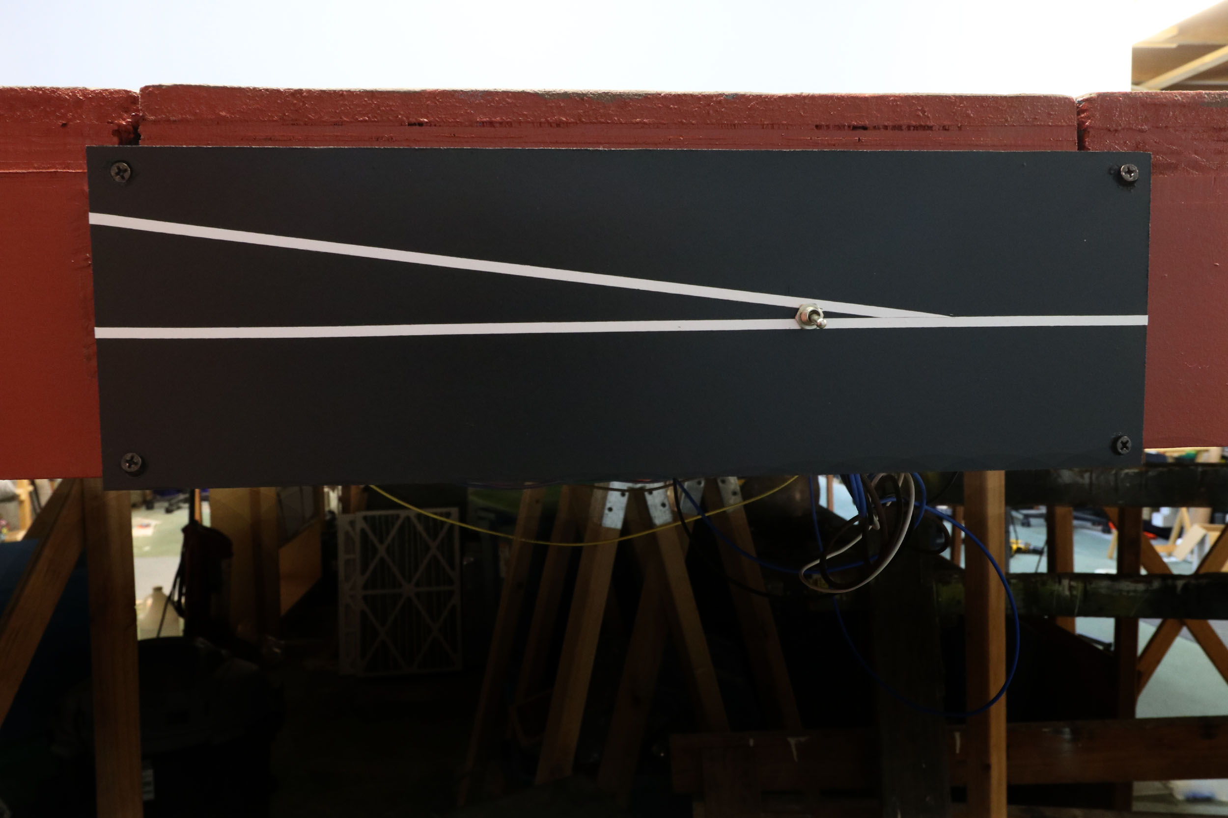
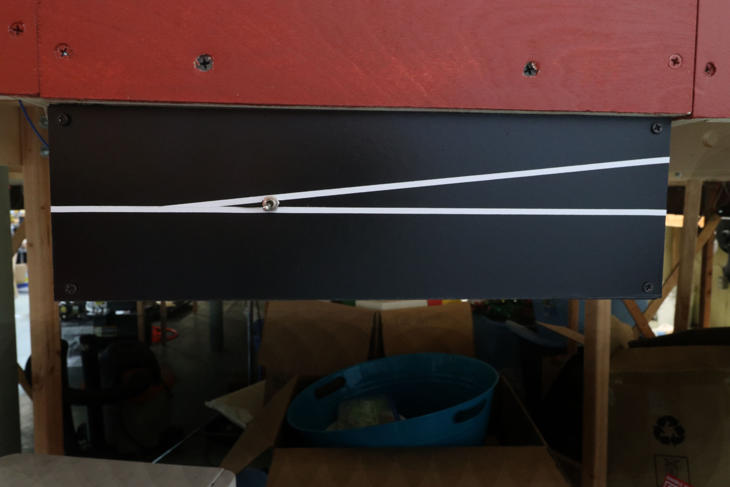
I made 4 all new local control panels in November 2020. I
probably could have made 2 of them smaller but wanted to match the size of the
original control panels. It is a LOT of work just to hold 7 toggle switches
total! I have not been able to replicate the bicolor LEDS for the new panels. I
have not found my LED supply yet.
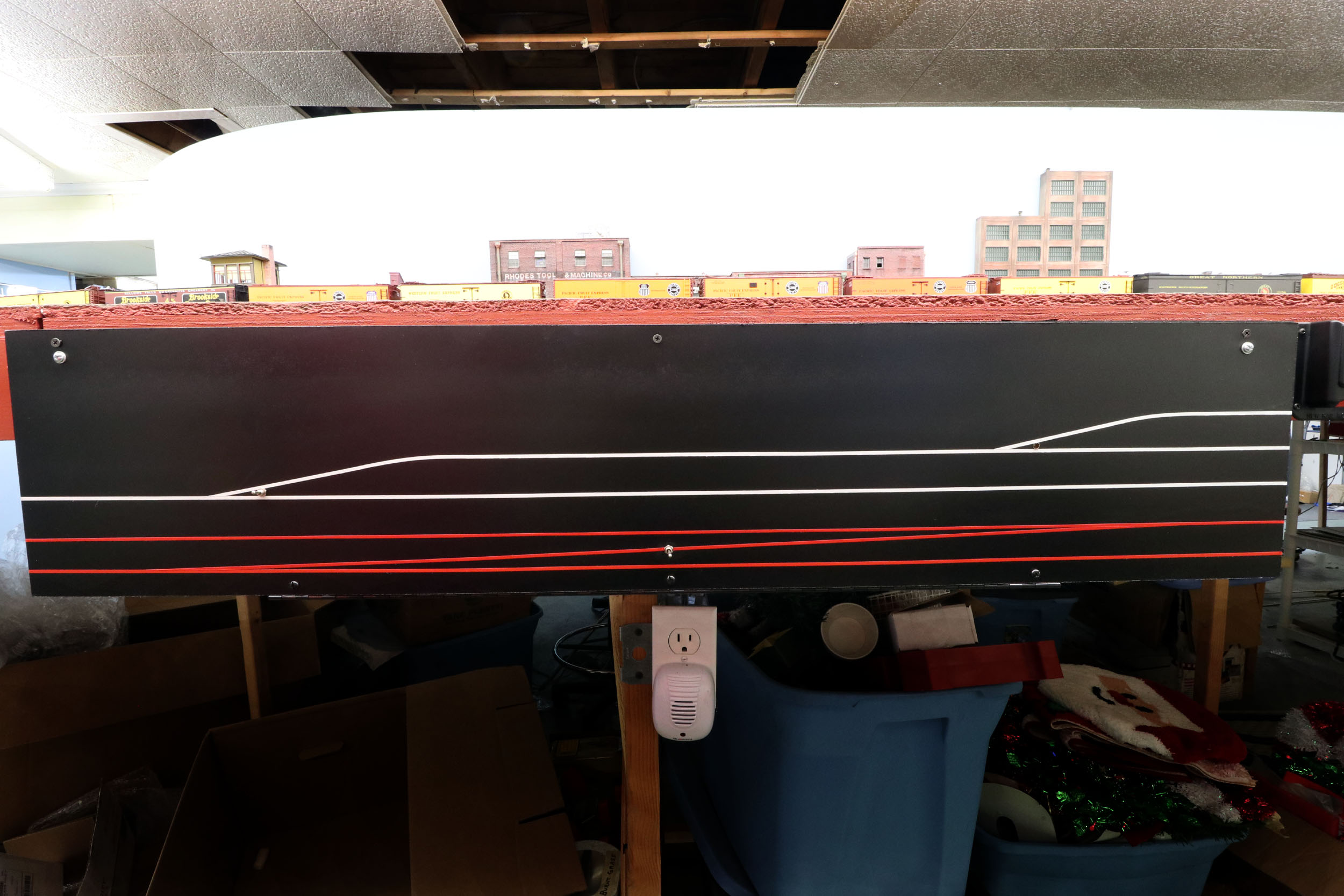
These are very small panels at the ends of the layout about 4” x
13”. I recessed 1 panel under the layout because it is an aisle way pinch point
to closets in the end of the basement.
Turnouts
I sometimes question to my decision to make the frogs live and
points dead. It works well with the stall motors but can be a
maintenance issue cleaning the points contact area. If I had plastic throw bars I would not have
to isolate the points.
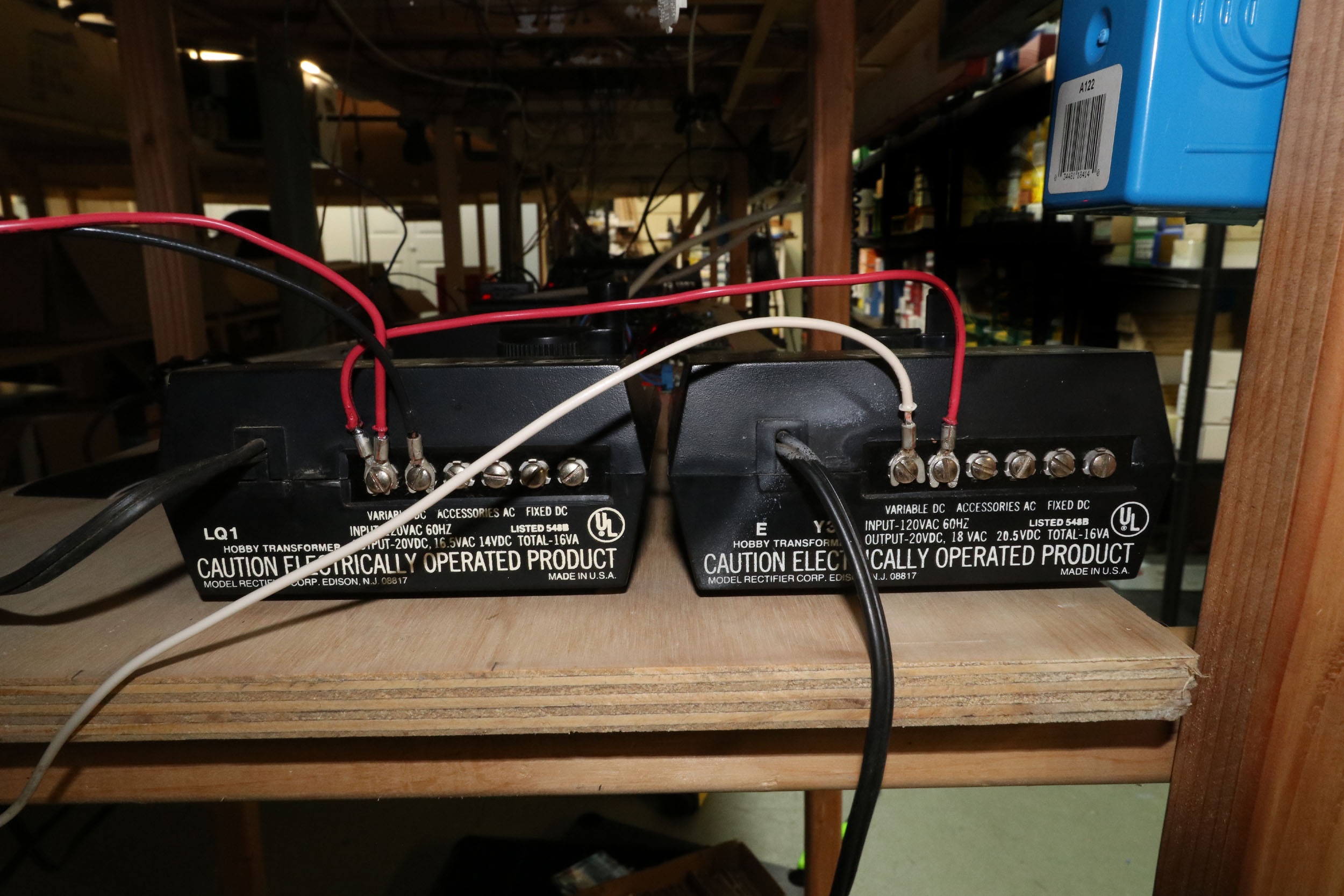
I decided to power all turnouts, including 2 that were ground
throws that are very accessible right at the edge of the layout. I recently had
issues with the power packs for the turnouts getting hot and shutting down.
Powering 40 turnout motors was probably at the maximum. Adding 7 more turnout
motors to the load was not going to help, so I isolated the layout in the same
way as the DCC power buss for the turnout power and got 2 more transformers.
These are MRC TechII 2500 transformers.
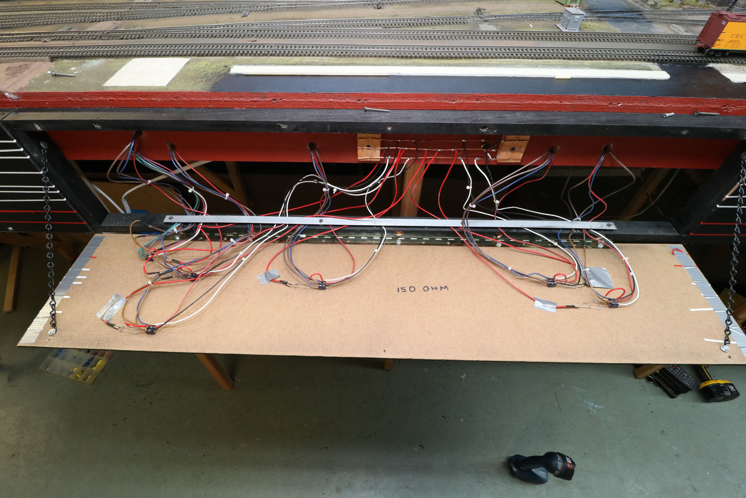
I would like to mention the wiring system for powering the
turnout motors. I don’t completely understand it but by using the variable
outputs with 2 transformers set to opposite direction creates 3 wires I have
made as black, white and red. I use the variable outputs because the turnout
motors are rated at 3 volts. I am set to about 2 volts.
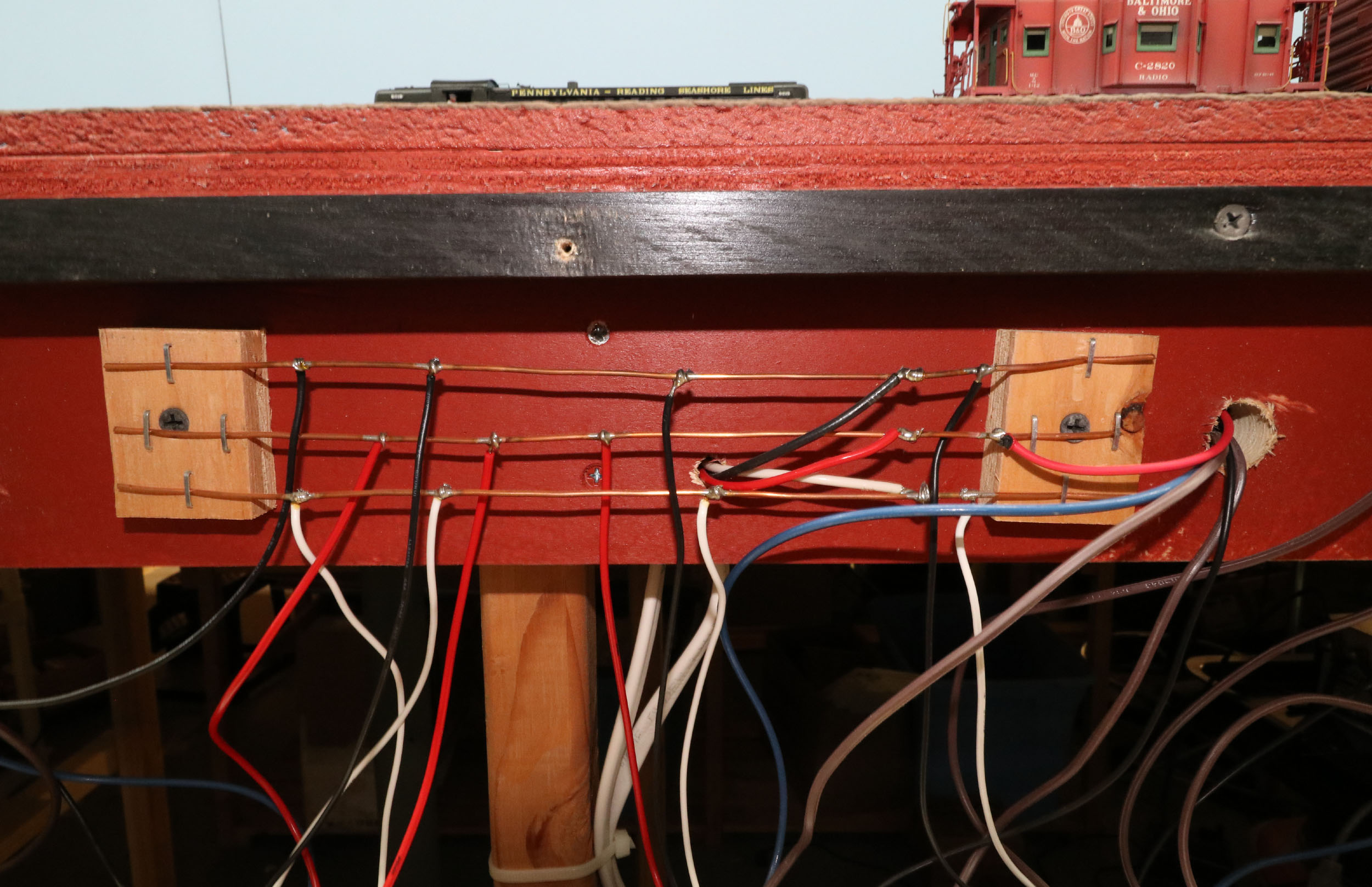
The turnouts are controlled and powered for the motor and
flipping DCC frog polarity using a single DPDT toggle switch.
Red goes to 1 motor lead. The other motor lead goes to center of
the toggle. Black and white goes to the top and bottom of the toggle. For the
other set of contacts the frog goes to center. Track power goes to top and
bottom of the toggle. Crossovers are more complex but I use a TPDT toggle
switch still controlling everything with 1 switch. The other turnout motor gets
hooked in series in the opposite direction. The extra set of contacts on the
TPDT toggle controls the second frog. It can be tricky getting the combinations
of turnout motor direction and frog polarity correct especially on a crossover.
Hopefully the explanation is clear enough to follow. Maybe make a diagram as
you read the explanation.
Ground
Throws To Turnout Motors
As I have mentioned the track plan evolved over time without a
real master plan. When I added the siding for the ice platform was mostly
because I already had everything I needed. So when I installed
a #6 turnout that put the throw bar right on top of a section joint I
just put a ground throw in. It was right at the layout ends and very
accessible. It was only recently I decided to power all turnouts. The turnout
at the opposite end of the layout is my only #5 and a bit shorter so I was able
to power it easily.
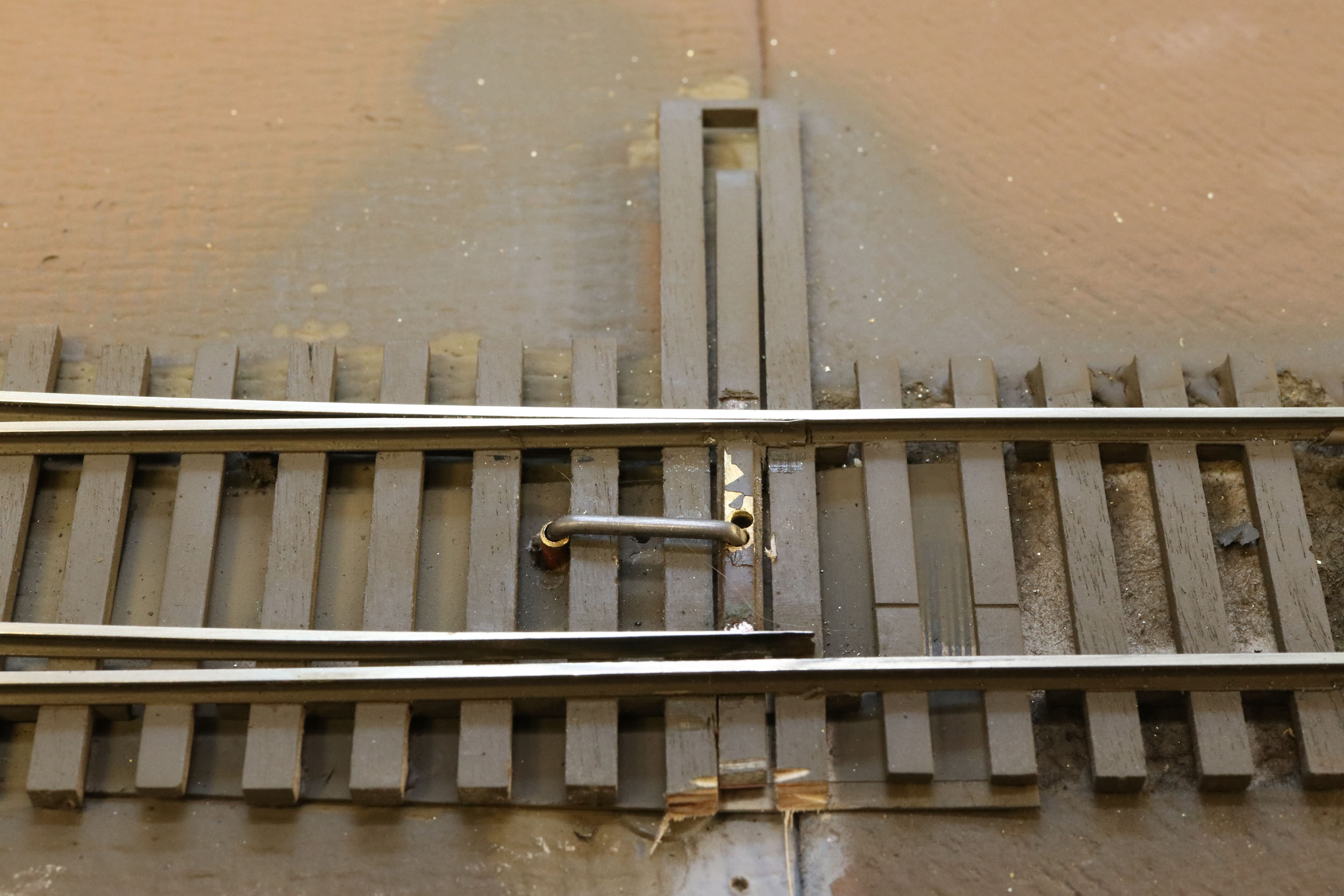
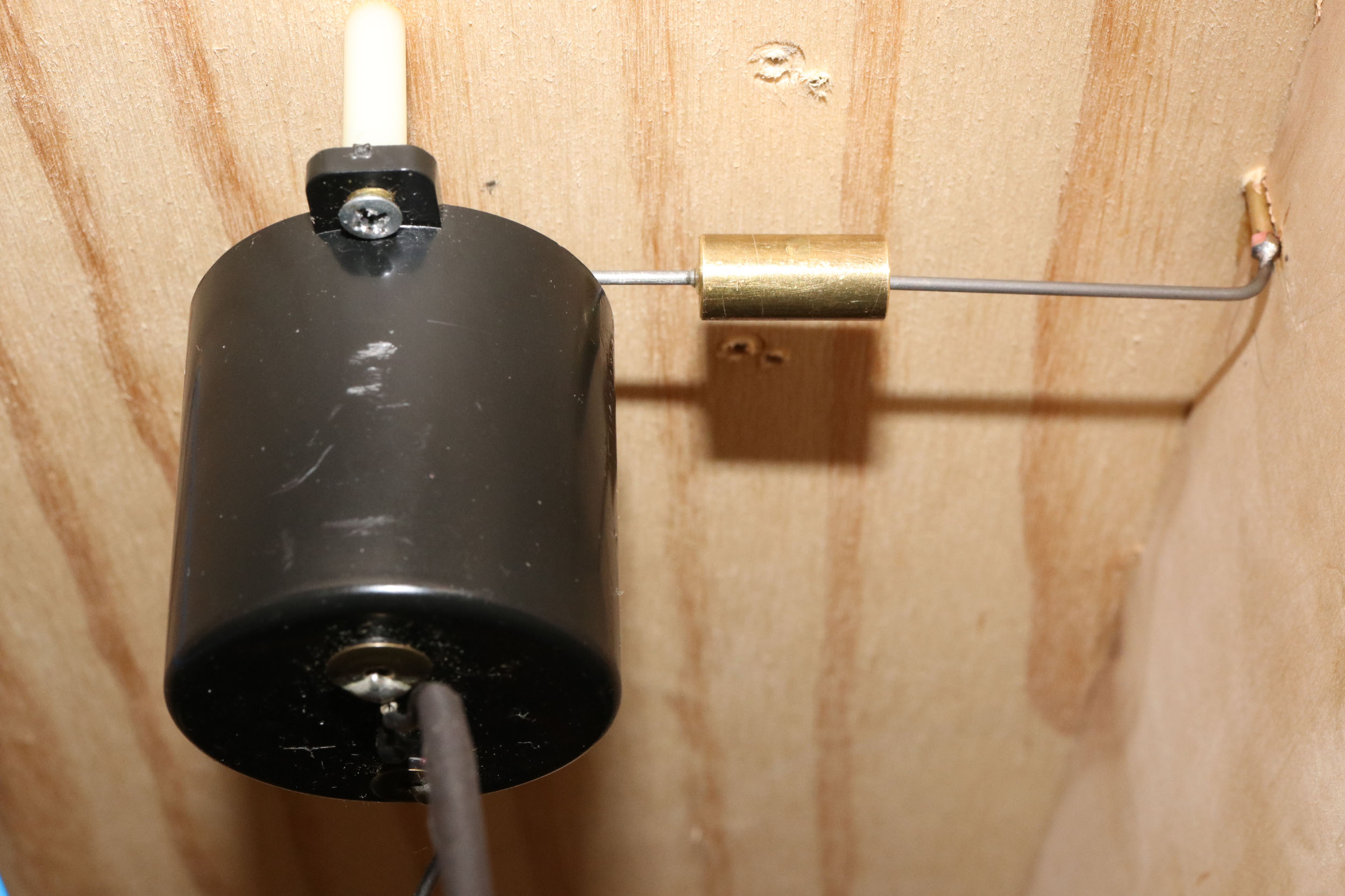
Powering this turnout was a bit of a happy challenge to make the
linkage. For all other motors the wire to the throw bar is vertical directly
swinging to move the turnout. But some
of it goes back to what I learned in 1977 at the HO club I belonged to. We
powered MANY turnouts with this wire “J” lever setup and twin coil switch
machines. It is .062 steel music wire – very difficult
to bend - into a J shape. The wire rotates in a brass tube through the layout.
Note that I still JUST missed a frame member with the brass tube. I soldered a
brass nut to the bottom of the wire to keep it from popping out of the turnout.
There is also music wire inserted in the motor of equal length lever to the
linkage. This brass round stock coupling idea just came to me as I was looking
at it. It is a tight fit on the motor wire but a larger hole for the linkage.
The larger hole allows for room to pivot in the brass round stock as the motor
rotates. I pretty much got it right the first time. Solving stuff like this is
just big fun for me. I like the challenge and then making whatever I needed.
Added
11-17-20
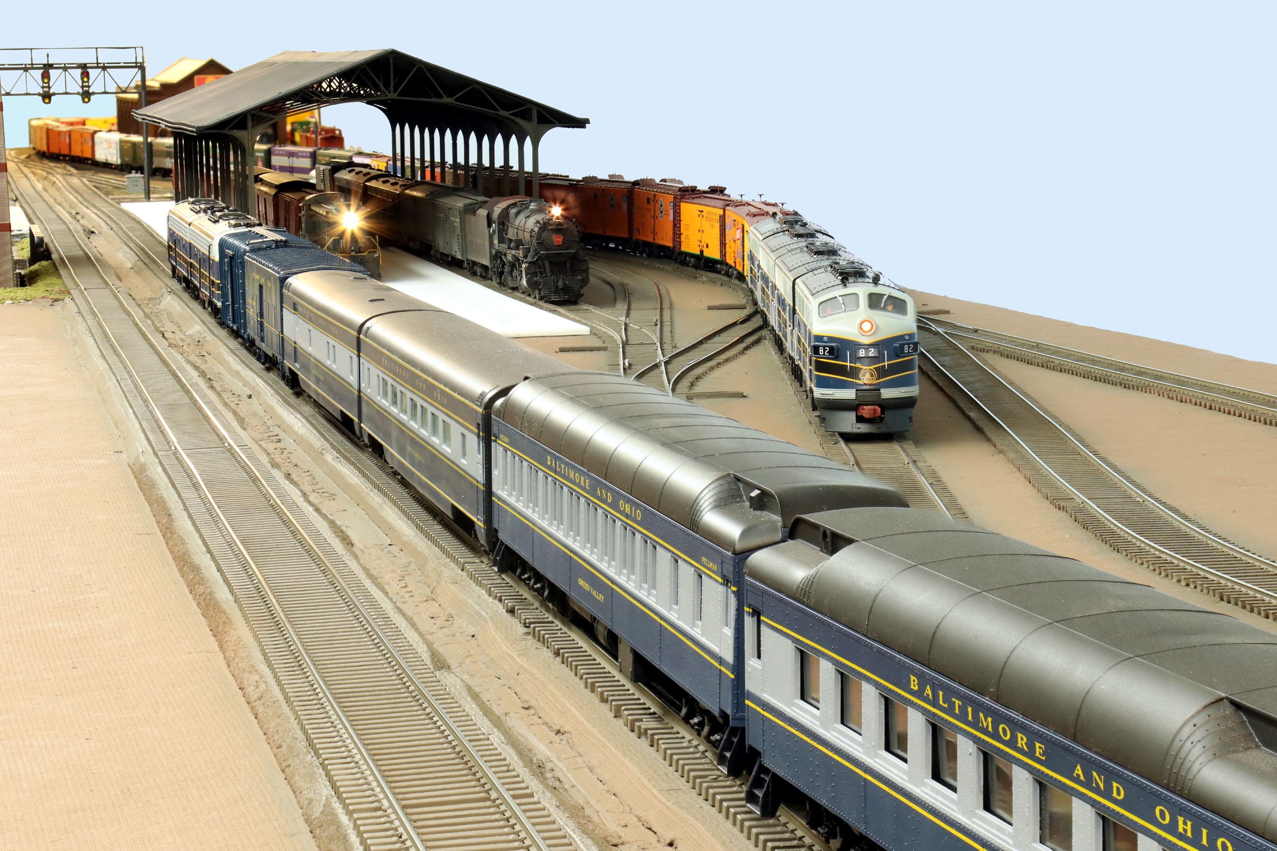
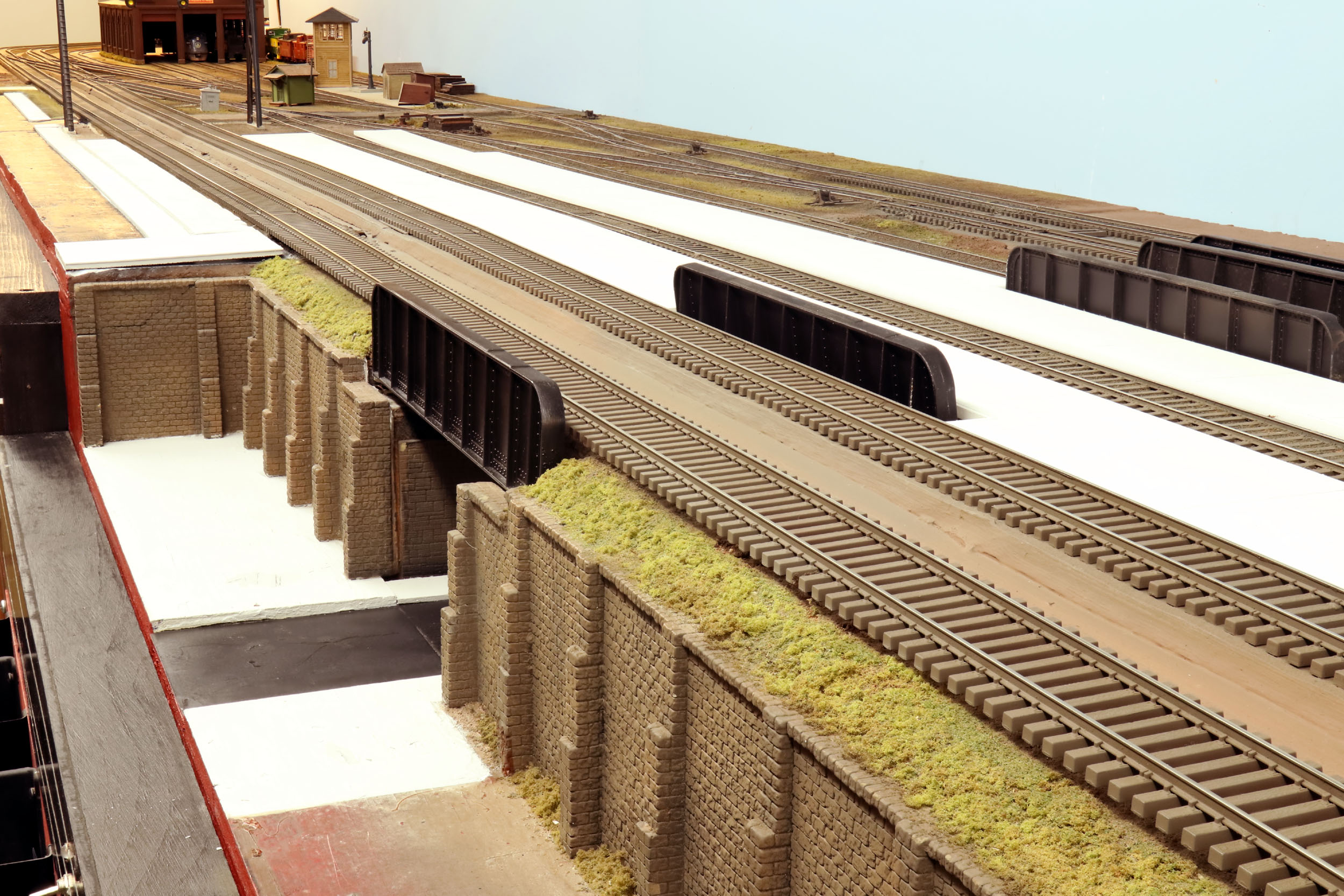
Station
Platforms
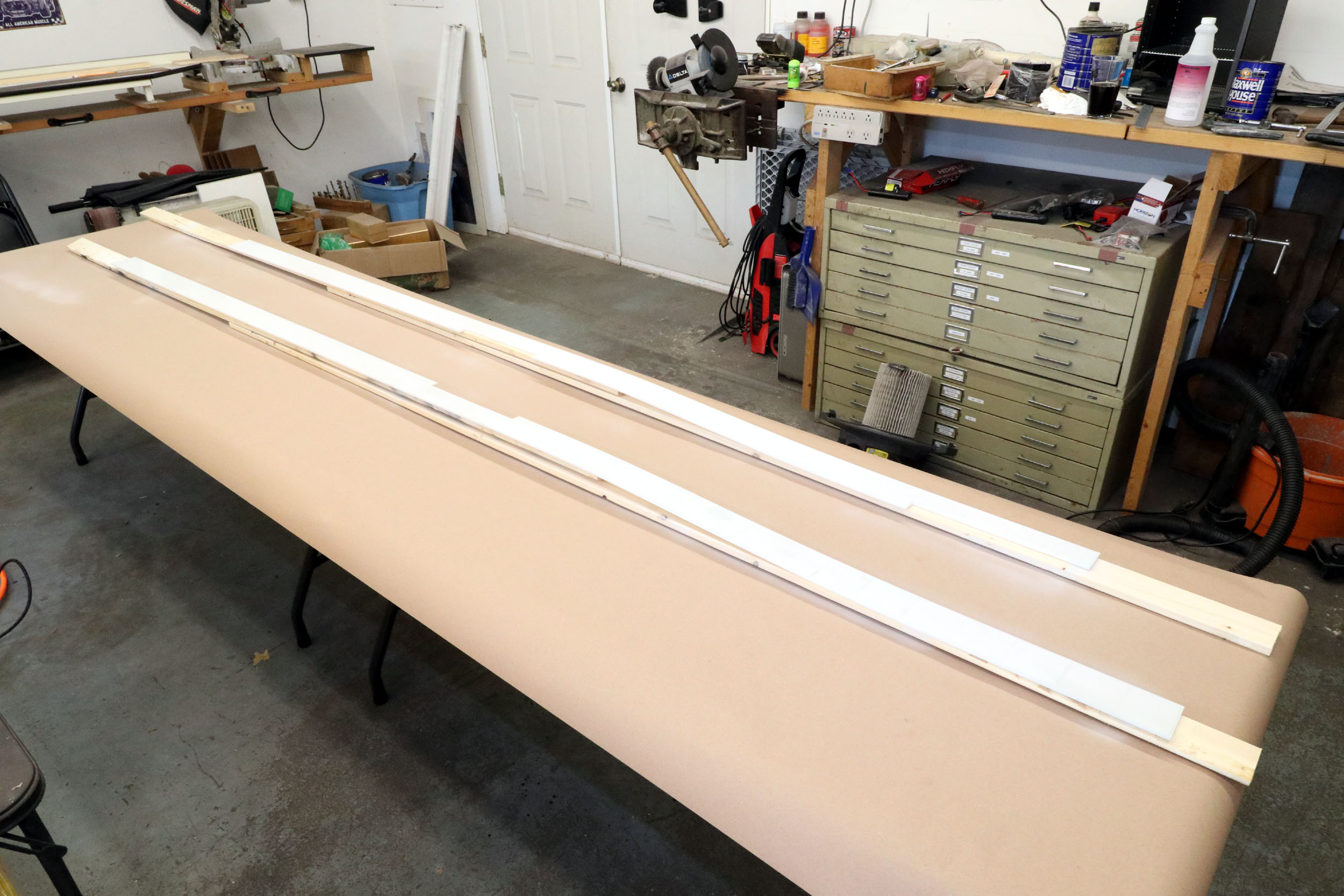
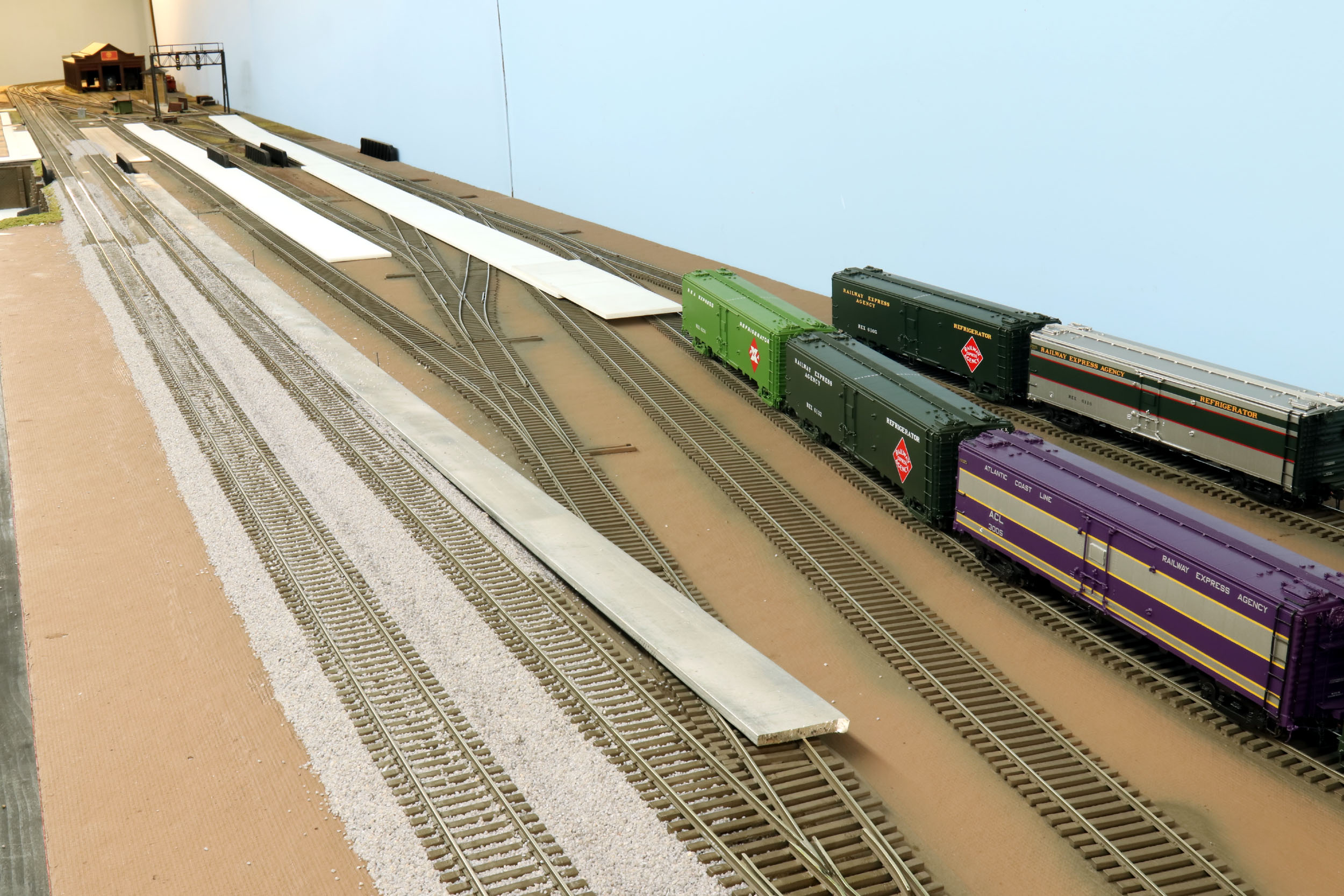
The one side of the layout has long been designed as a passenger
station even before I owned it when it was Don Dewitt’s modules. Don made thin
plastic sheet lamented to balsa wood for the platforms. They were about 6 feet
long as well. I replaced them with white Plexiglas that is 10 feet long and
slightly shiny and translucent. I added a 24” piece so 1 platform is 12 feet
long. If I am going to make a passenger station I might as well make it usable
for S Scale. S passenger trains are not usually only 6 feet long, at least when
I run my trains.
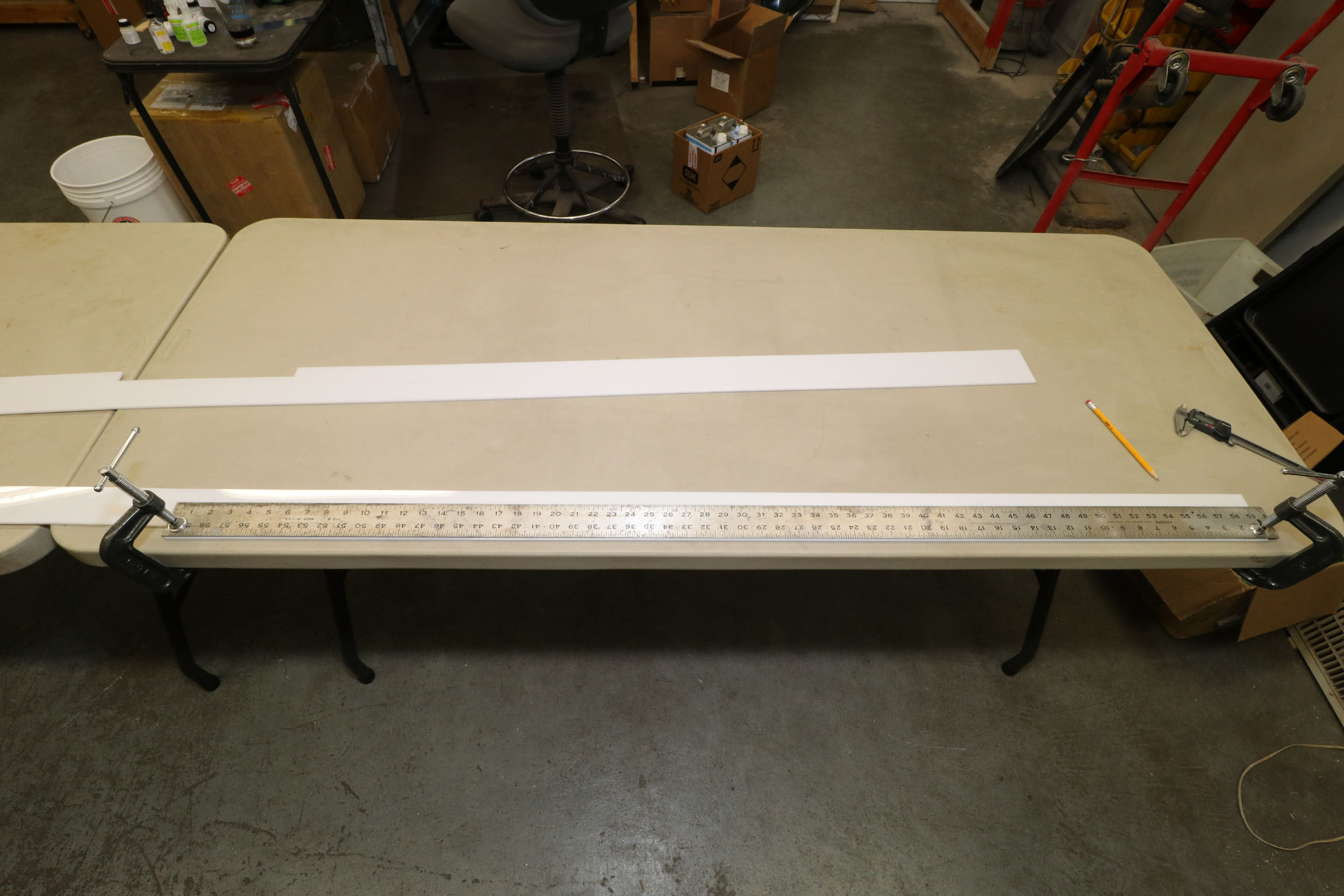
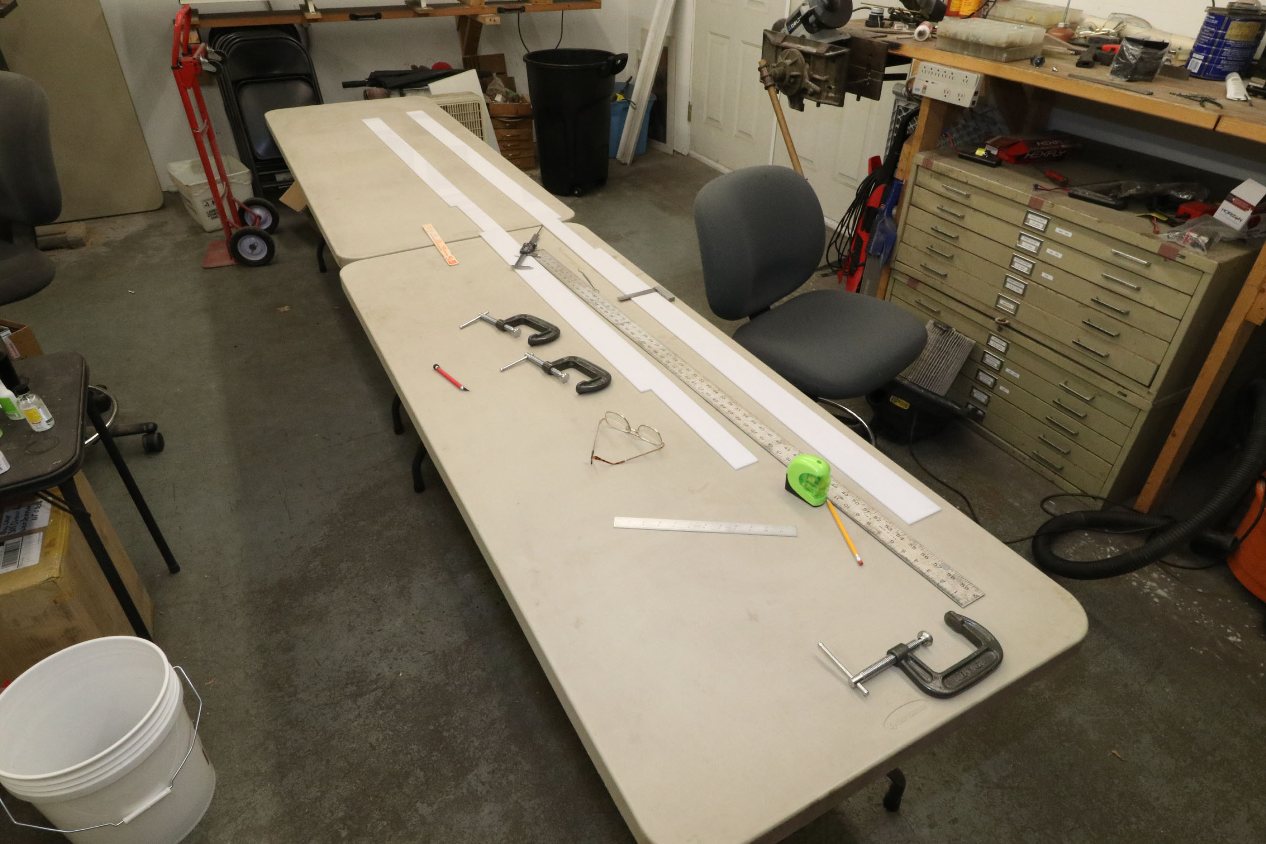
I have had the Plexiglas for many years now for what I finally
did this week. Micromark sells a “tool” for scribing
plastic. It turned out to just be a dental pick with a flat spot ground on it
but it does work by removing a sliver of material. Since the platforms are
Plexiglas it is a lot harder than styrene. I had to make 4-5 passes to make
sure the line was scribed. Having my workshop made all the difference in these
projects. I just set up some tables and got started. I have a 60” long steel
ruler that made the scribing much easier as well.
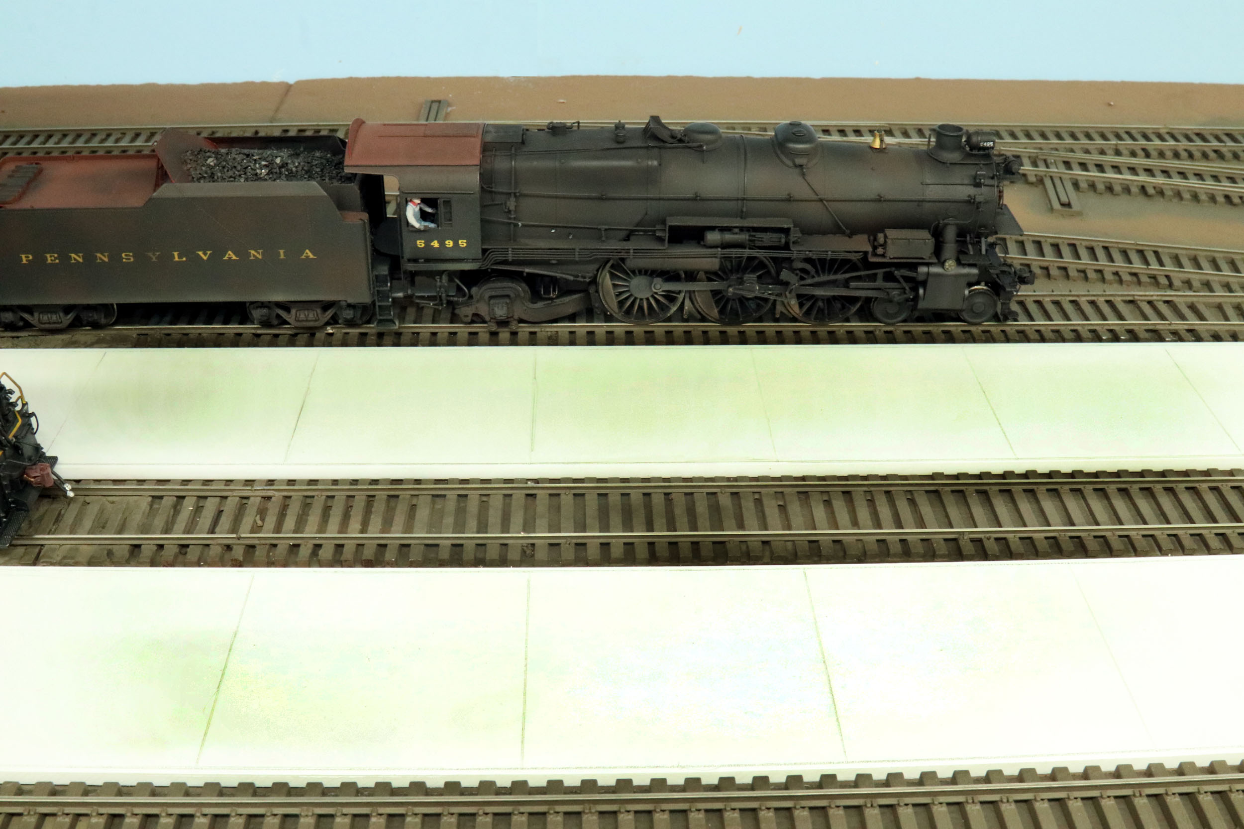
I spent some time trying to find a flat color to paint the
platforms that I liked. For all the train paints I saw “concrete” was a boring
gray color. Concrete is not truly white for long but I did not like gray
either. I settled on Tru Color Soo Line off white. I
liked it a lot. I can go back later and randomly weather a bit but for they are
good for now. There were some painting imperfections that I called happy
accidents. You have not lived until you airbrush something 10 feet long on a 25
feet long air hose. After painting I randomly lightly traced the scribed lines
with a pencil to accentuate them. I then sprayed Dullcoat on everything since
the Tru Color paint was slightly glossy. It is difficult to see the scribed
lines in the photo but has a nice effect when on the layout.
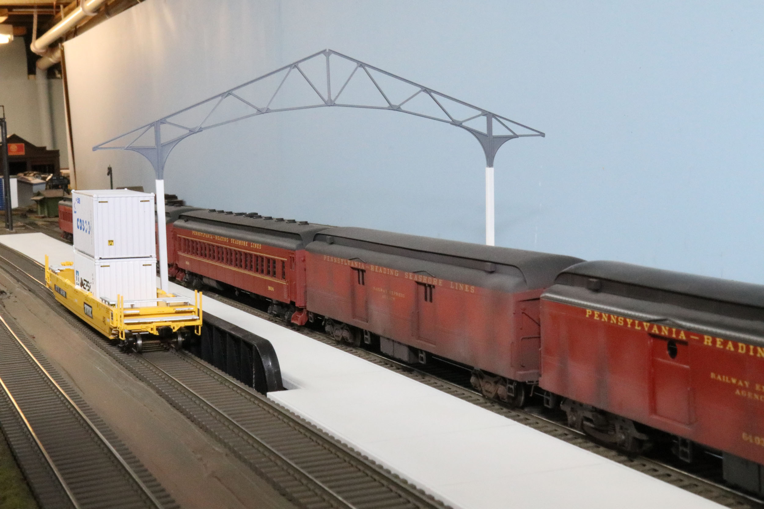
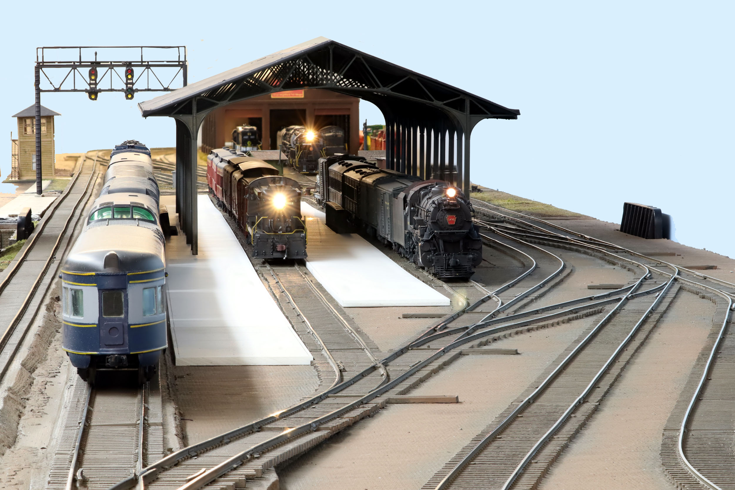
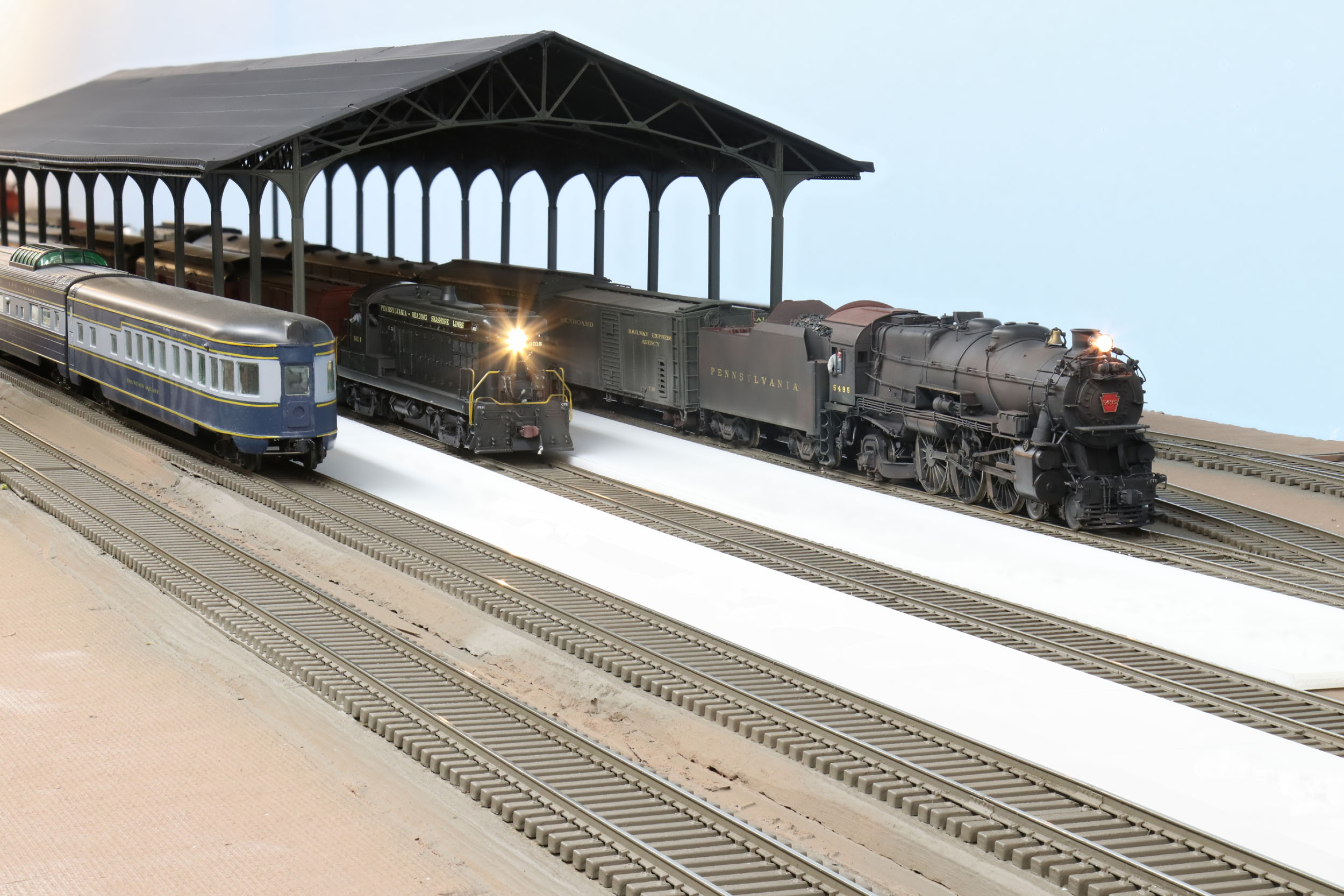
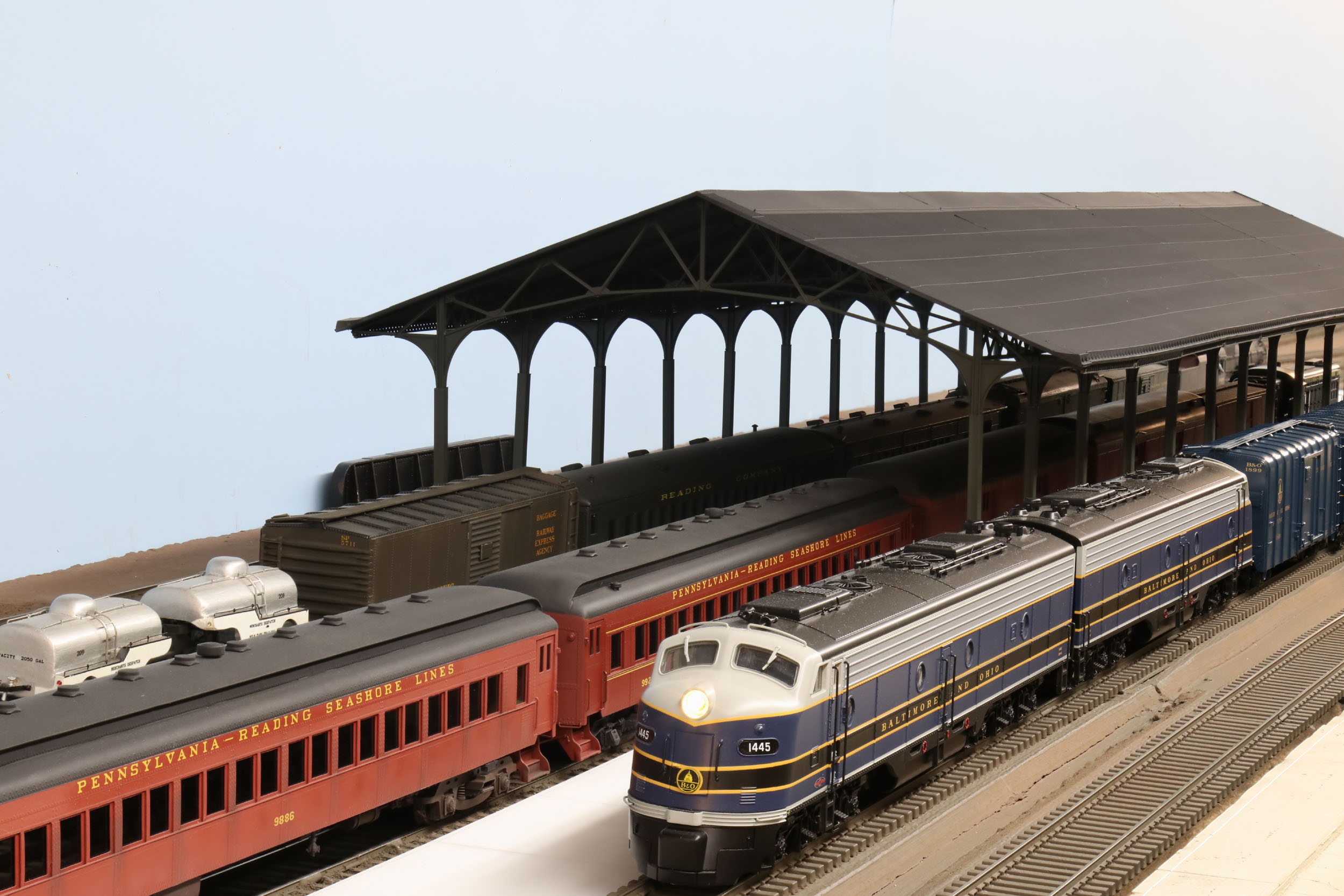
Station
Train Shed
Bill
Builds A Building!
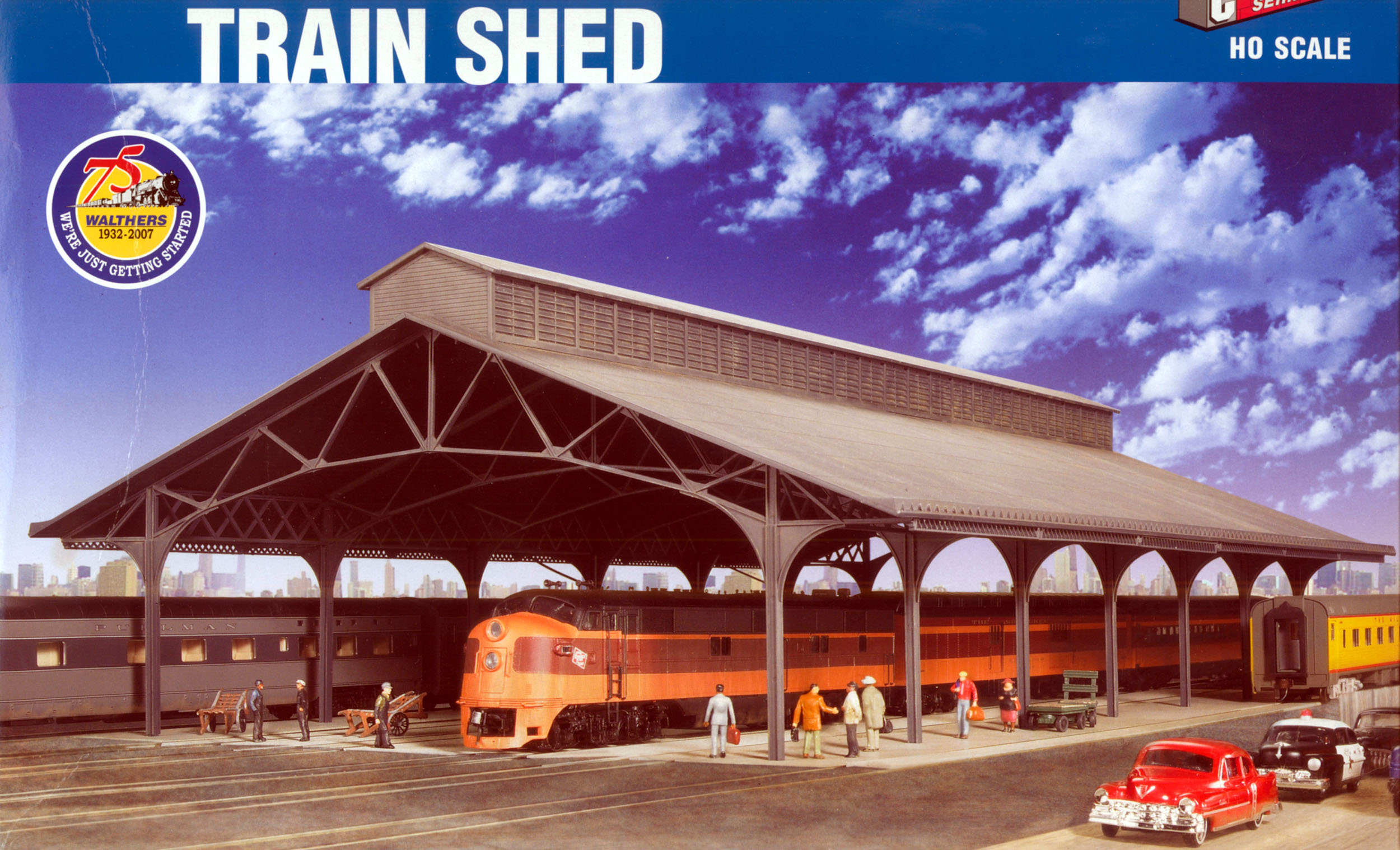
The streak has been broken. In the 33 years in S Scale I have
never once built a building. It mostly does not interest me. But the layout
improvement binge made it happen. This is the Walthers HO Milwaukee train shed.
I have also had this for many years. I got 2 kits that are expandable to be
about 48” long. I took 1 truss out of the box and eyed it many times to see if
the track spacing would work out. Short of designing the track to fit the shed
which I did not do, the spacing worked out really well.
The first thing needed was to decide how to raise the shed and
how high. I would have liked a H or I beam like the
original but it had to be strong. Looking at Plastruct I did not see anything I
liked. But Evergreen had square tubing that was very close to the kit posts so
that is what I did. Evergreen 253 tubing slipped over the original I beam posts
with very minor sanding was the way to go. It was strong and had a natural stop
at the top where the trusses branch out for an equal and accurate height
extension.
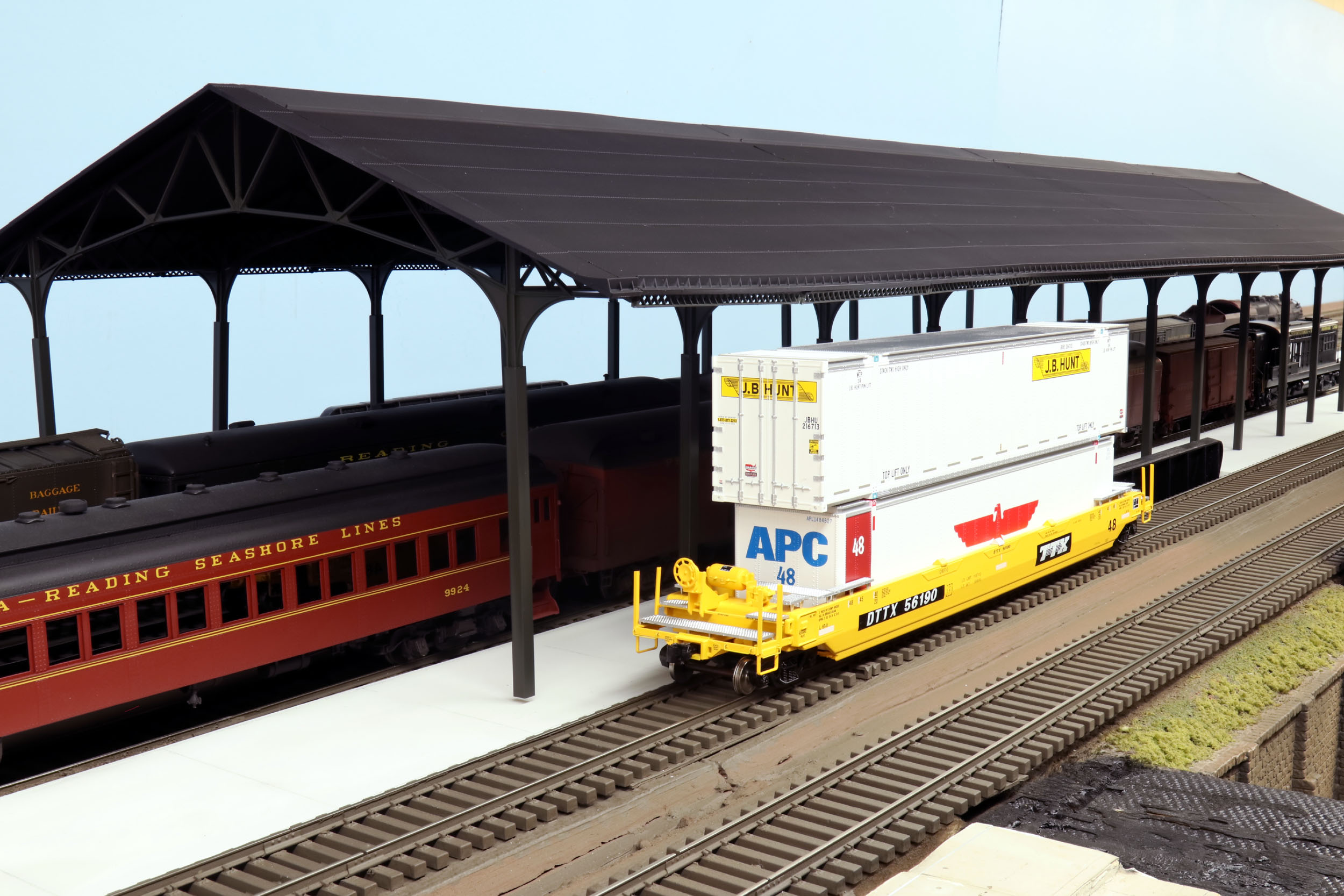
Up next was how much to raise the shed. A major factor was
clearing the inside mainline and being able to run double stack container cars
which I also have. The station shed overhangs the inside mainline. I absolutely
was not going to say “you can’t run this train there”. That violates my layout
design rule #1 - all trains must be able to run on all track no exceptions. My
first attempt was to raise it 2 ½” which I thought was too much. I settled on
raising the shed 2”or cutting tubing 4”long. This photo at is raised 2 ½”
Once the height was settled I just had to get through the
assembly which was quite the job. The directions were a single drawing and was
lacking at that. I quickly found it was not a well designed kit especially when
it comes to extending the shed. There could have been notches and bosses to
help with locating parts better. A butt joint for the roof sections made hiding
the seams impossible. A lap joint would have been much better. You need the
roof sections to build out from. If they are not right the rest is not going to
fit correctly.
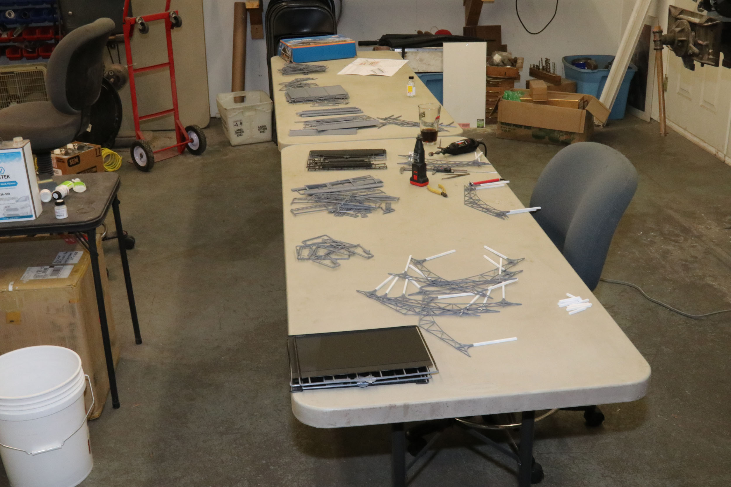
I assembled a single section at a time with 2 trusses each then
joined 2 sections into 1. I figured jointing them vertically was best. The
first time went pretty well. But I found you get ONE chance at quickly lining
everything up perfectly. It you have to redo the roof joint is roughed up with
glue and will be a problem. I needed a table top light so I got the Mag light from my milling machine and used a saw blade!
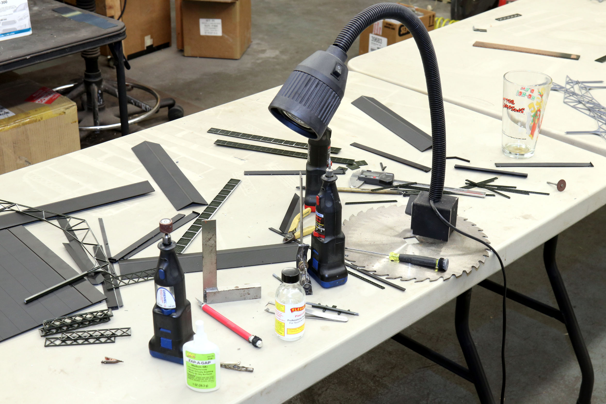
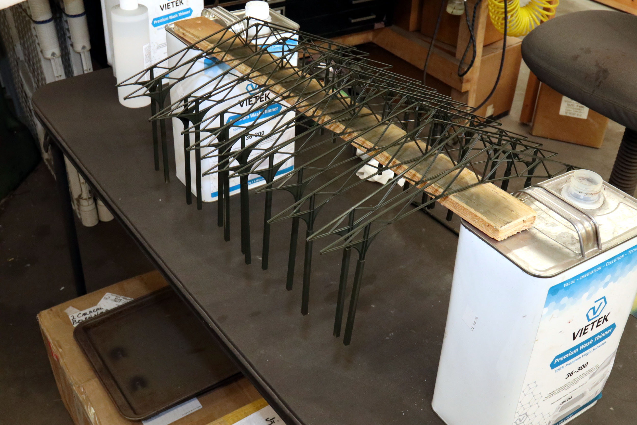
Speaking of glue any thoughts of delicate “glue control” quickly
ended. I used about ¾ of an ounce of Zap A Gap ACC
glue. I wanted it to be strong and not come apart – ever.
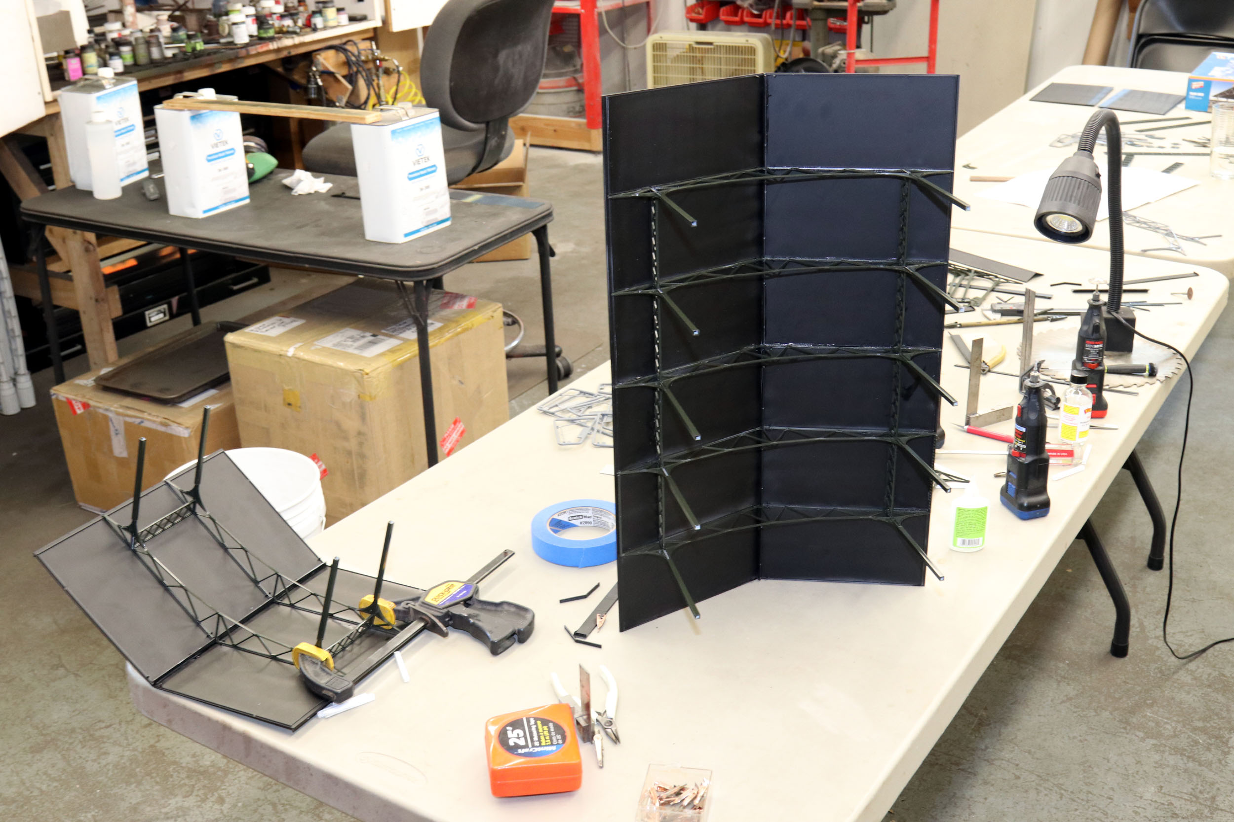
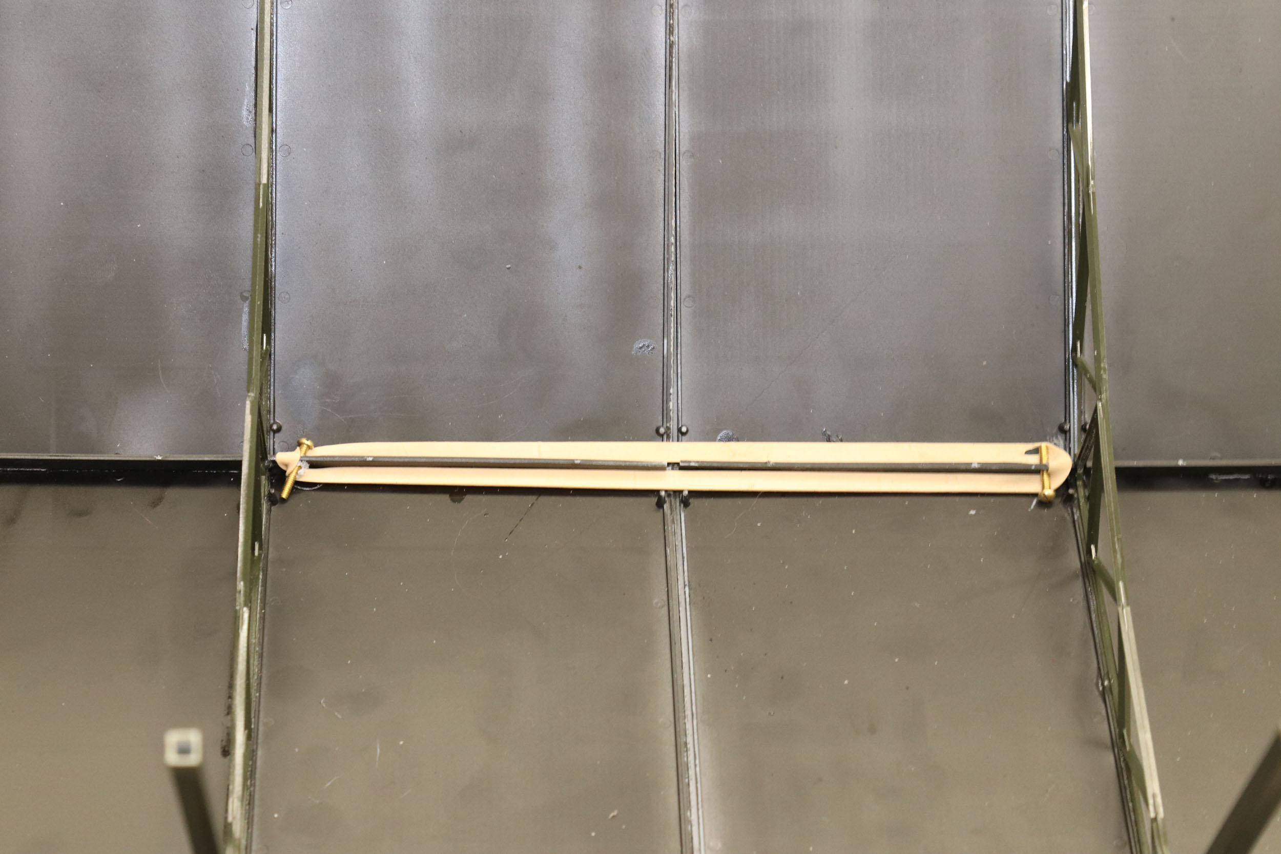
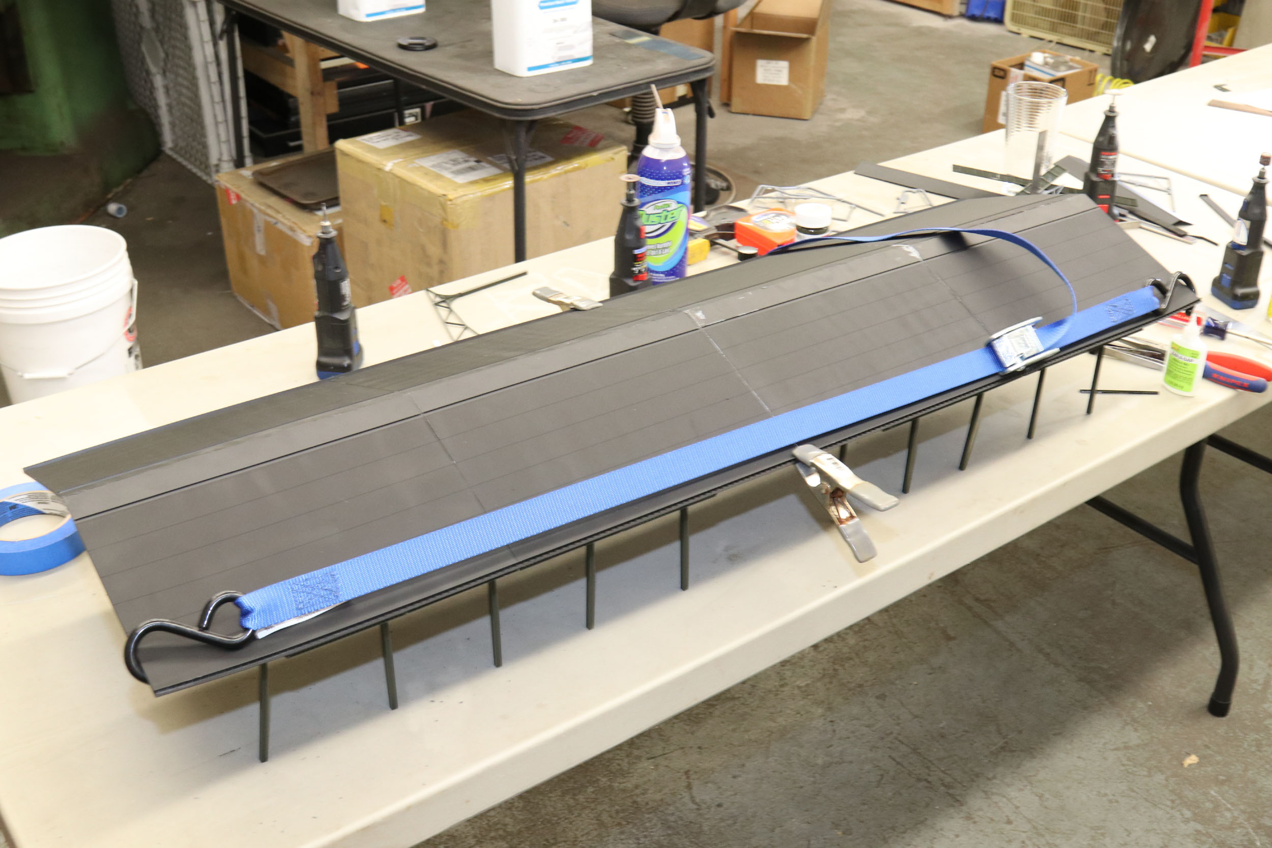
Joining the 2) 24” sections together is exactly when all the
“fun” ended and extreme aggravation started. I mostly embrace the challenge of
figuring stuff out but I had to get medieval on this thing after 4 attempts of
joining the sections did not go well. I rigged a rubber band in the underside of
the roof peak. I started by gluing 1 edge and worked towards the peak. I had to
get a pull strap to hold the other edge in place while I glued it. I am not
going to add the roof cupola vents that came in the kit. I don’t like it but it
would have shown the Pullman Green that I painted the trusses and structure.
I came really close to lowering the shed ½” after it was mostly
built or really raising it 1 ½” until I changed containers on the stack car
that were higher than my initial test. The current height is growing on me.
Depending on the shed positioning it does overhang the mainline. No need to
build in possible clearance issues. I am good.
I am mostly not into layout lighting but it is too dark under
the shed so that is next to add maybe 10 LEDs. That
will make the shed really POP when taking photos.
Added
11-21-20
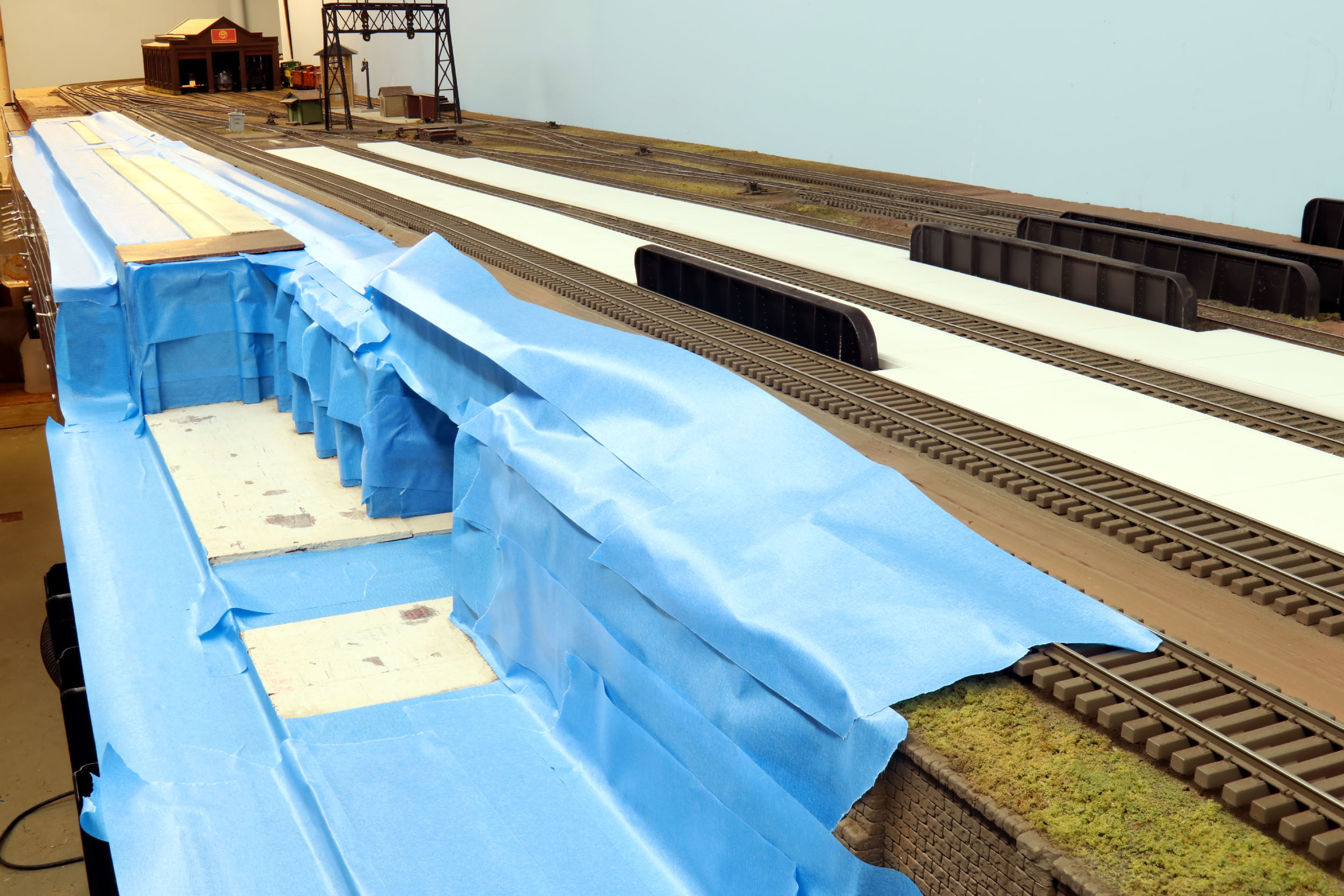
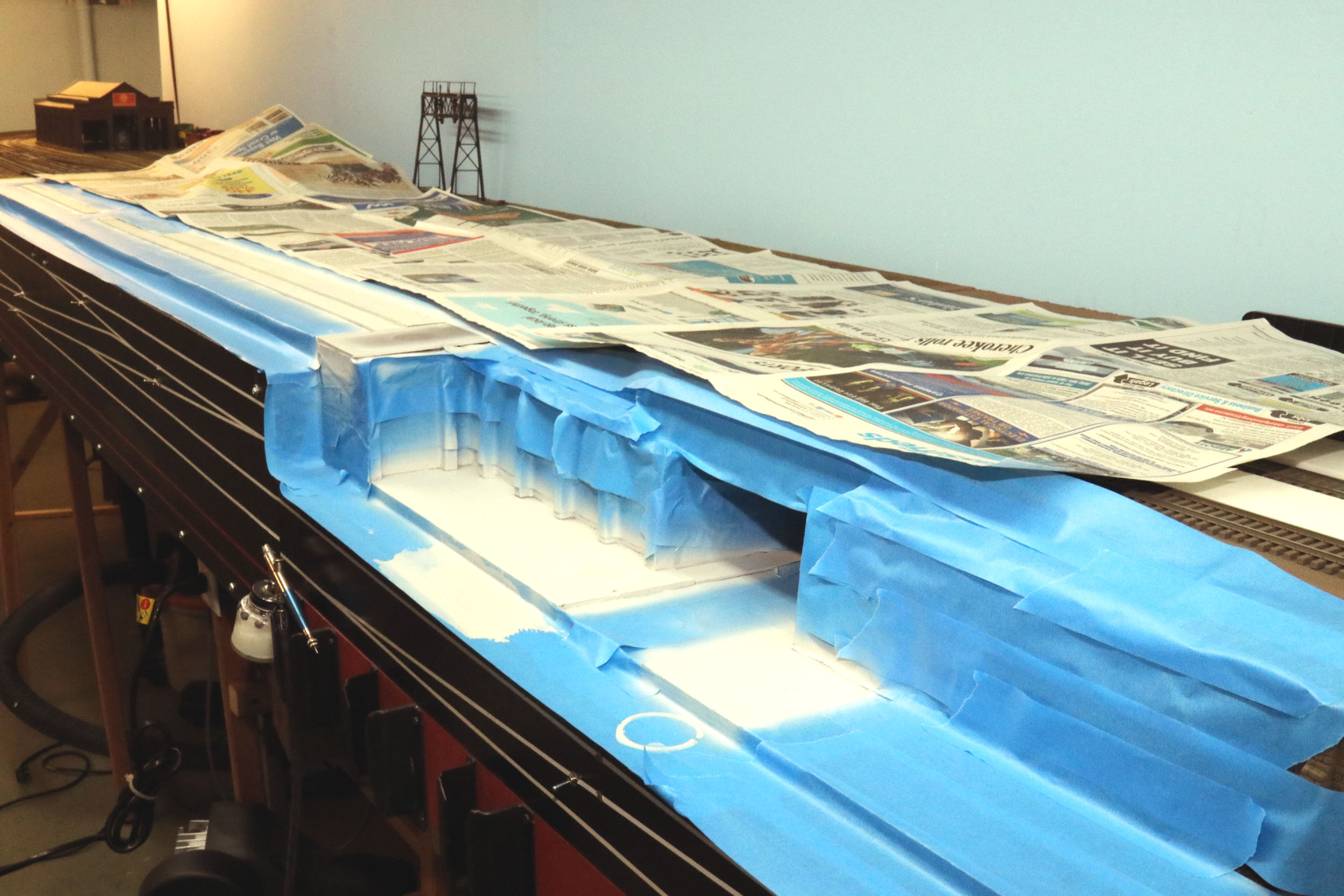
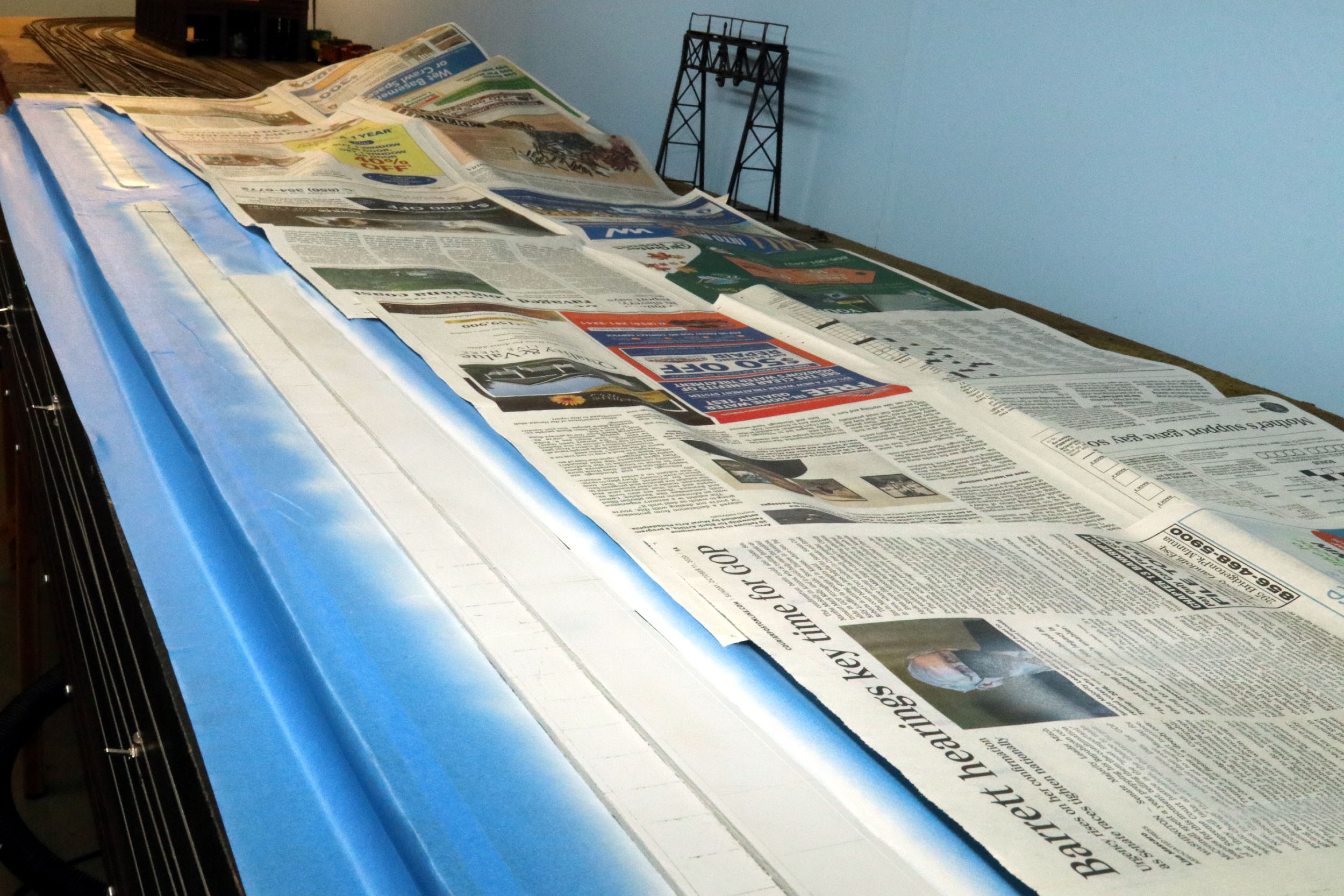
Painting
The Sidewalks
I have wanted to paint these sidewalks for years. It is well
known that I absolutely hate masking especially steam locos. But this needed to
get done before I started ballasting. I like the blue painters tape because it
is just the right amount of sticky. Note I came way too close to spilling the
paint down a control panel. The NCE handle brackets are a great place to put
the airbrush.
Added
11-24-20
More
Ballast!
My goal is to have the layout ballast done by the end of winter
2021. I started at the one end of the layout where I left off 2 years ago. I
went off into a brief attempt at using artist’s matte medium for ballast glue.
It was supposed to be better than white glue as drying flat and sound
deadening. It is expensive - about $1.00 per ounce! Maybe I cut it too much 1/3
matte to 2/3 water but it did not hold at all. I went back to Elmer’s white
glue at close to a 50/50 mix. That worked well. It is rock solid now.
The ballast dispenser I made works well. I get about 6 feet
deposited in 10 seconds with a fill up. However it fills to the top of the
rails with ballast that has to be pushed forward but still is better than
nothing. That is so tedious and time consuming to get the ballast perfect
before gluing. I am waiting for casting kits to be made so I can upgrade the 3)
#6 turnouts on the inside mainline. They will not get ballasted for now. The
aluminum flat bar was placed to hold the ballast to a minimum tight against the
ends of the ties. The station platform is normally there. I figured the white
glue would not stick to aluminum, and it did not.
Added
11-28-20
Grade
Crossing
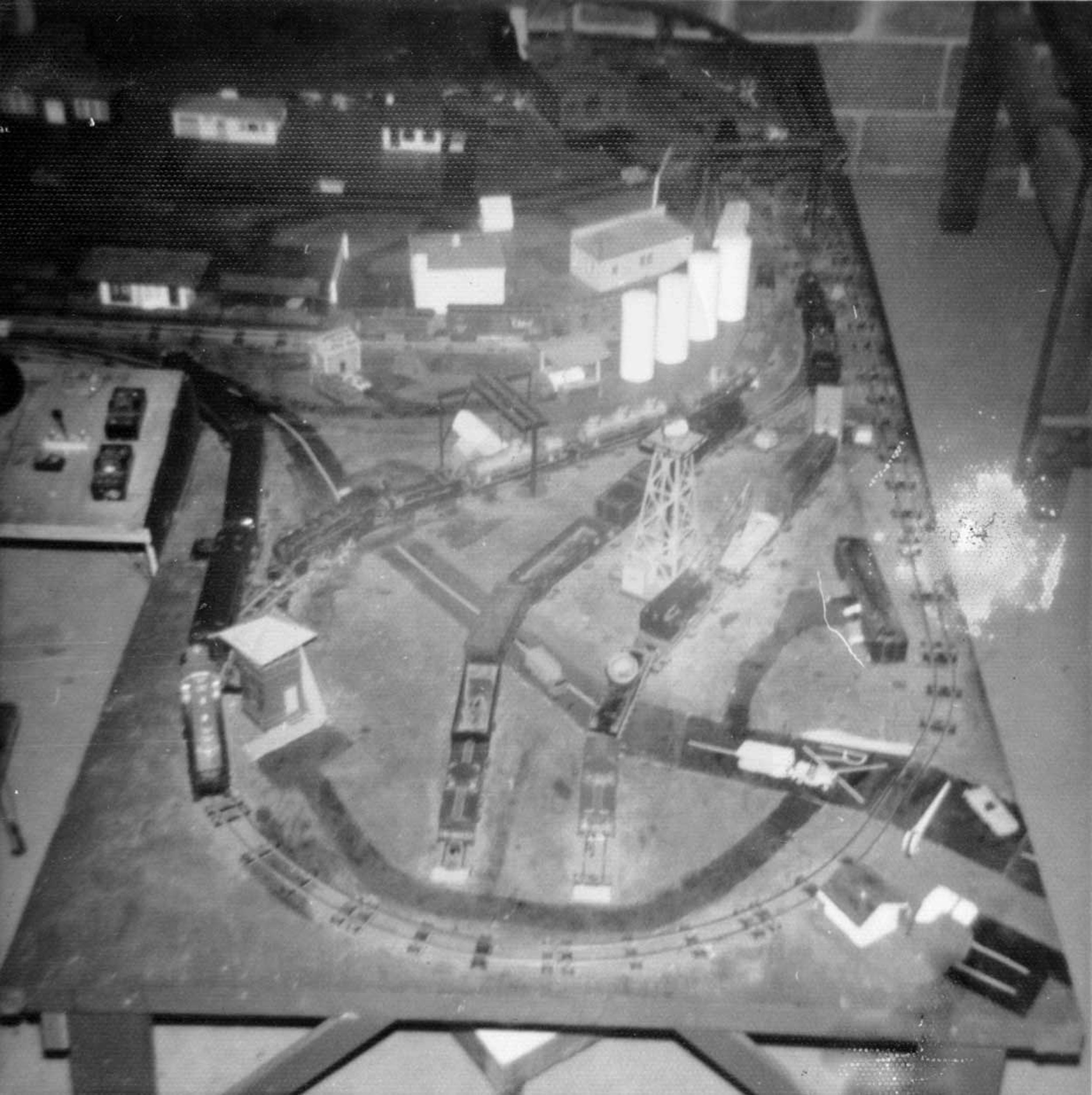
Below is the first grade crossing that I ever made when I was
about 13 on my American Flyer layout. There were actually a few grade crossings
as that road crossed that yard. I went all way with my car pinstripe RR
crossing sign. It only took 45 years to make another one!
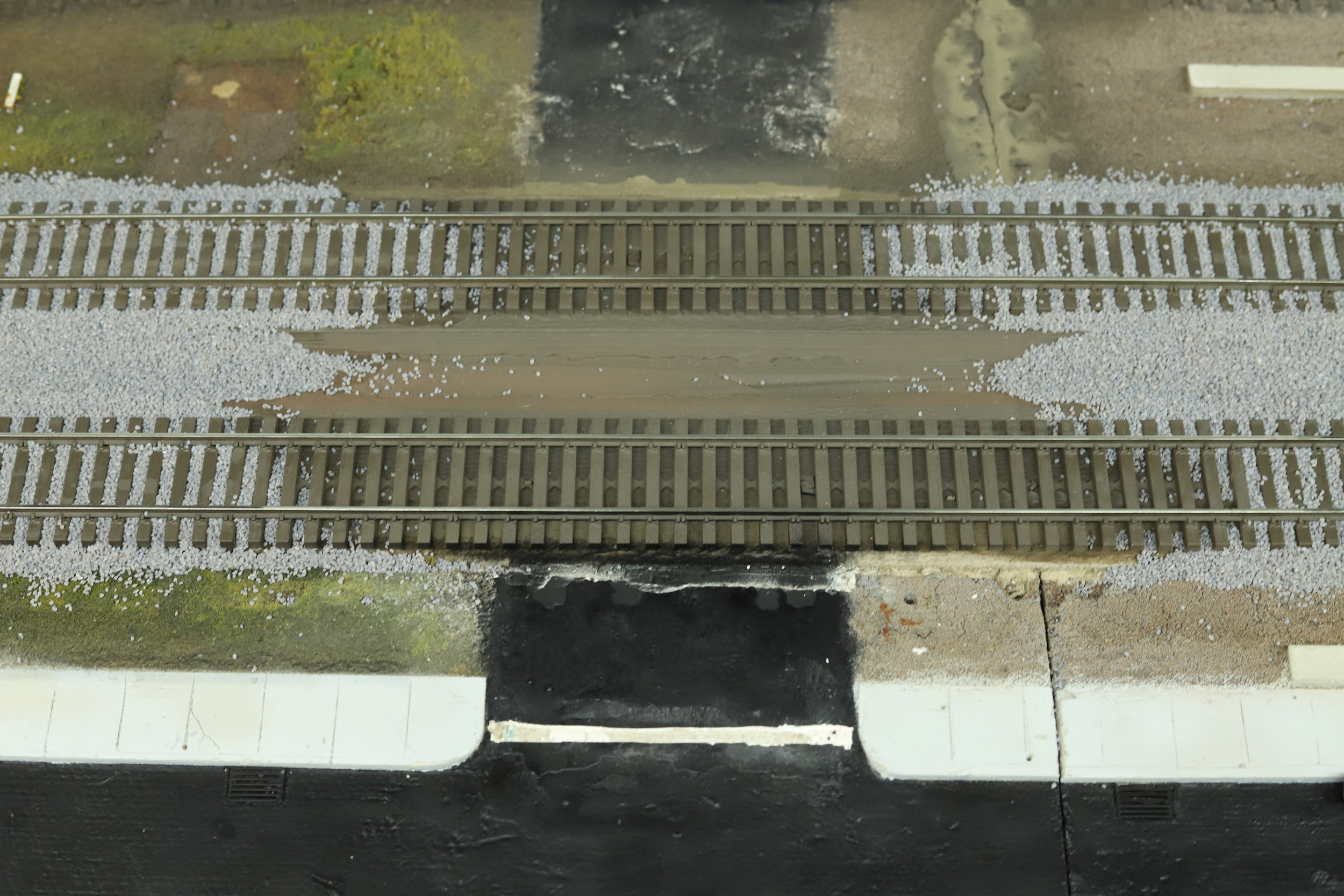
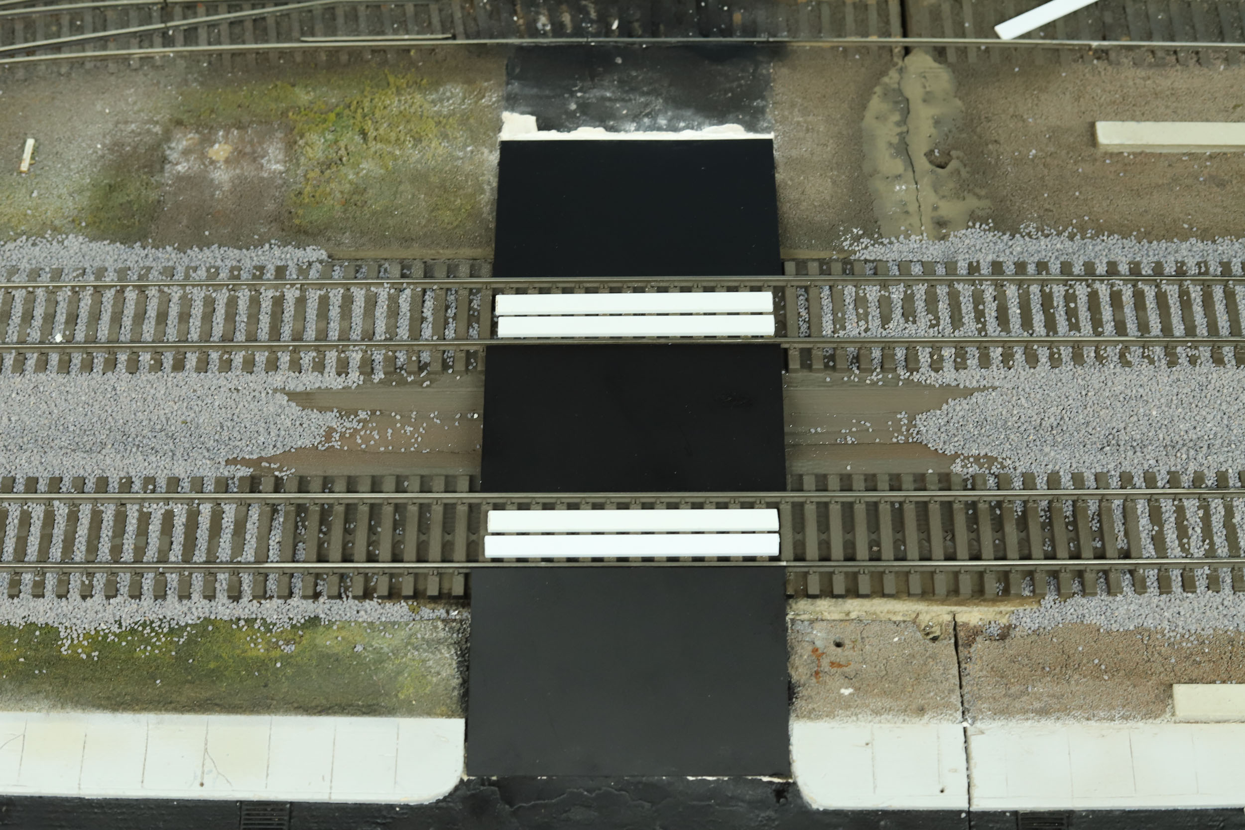
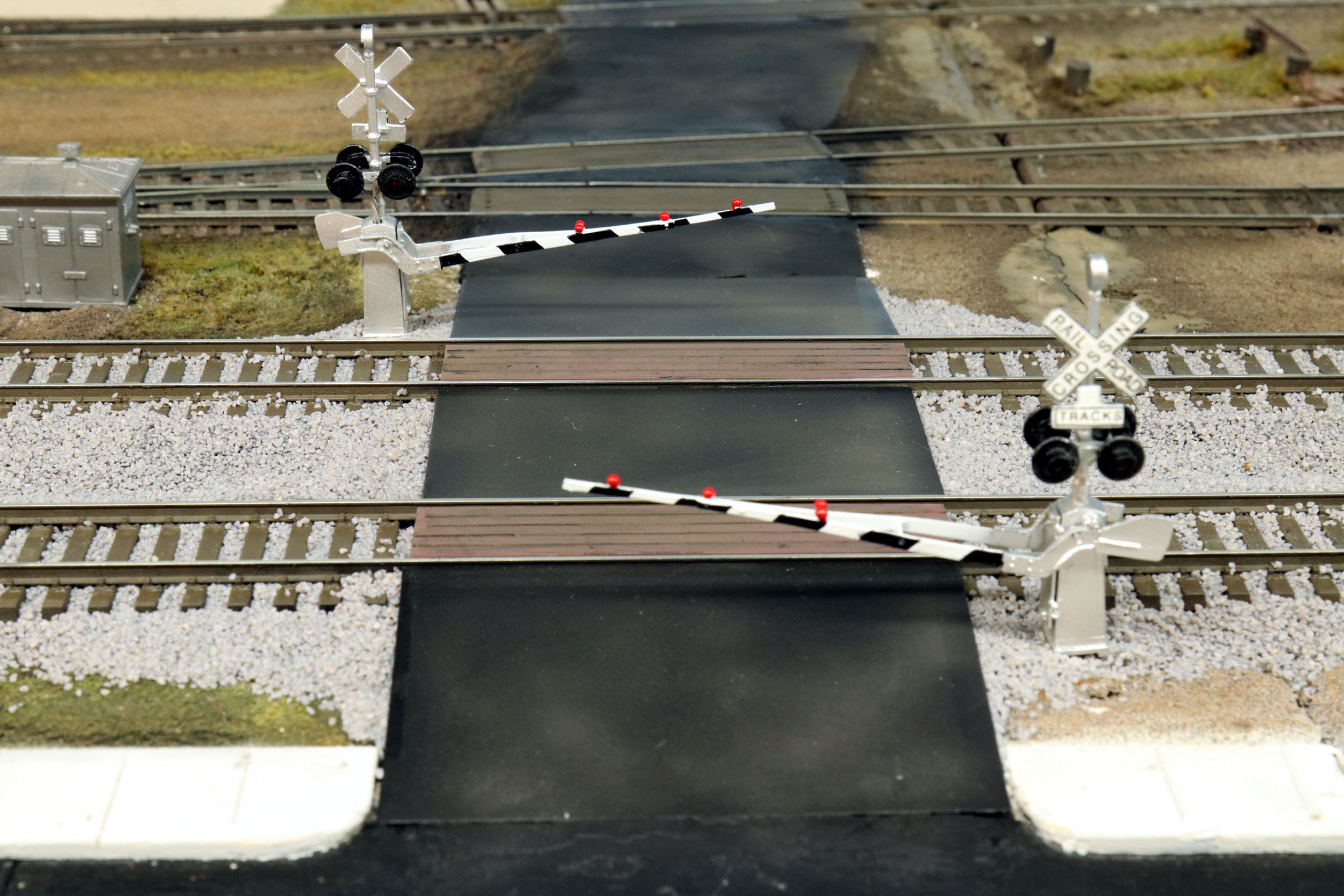
When I removed the code 100 mainlines and replaced them with the
code 138 track the grade crossing here was removed. Since I was finally
ballasting it needed to be replaced. I tried to not over think it. It was
pretty simple with Evergreen sheet styrene and strips. I decided to do the fill
in with ballast because the alternative would be messy spackle. I think it
worked out well. The NJ International crossbucks just
set the scene off. They do not flash or have lowering gates for now.
Revised 12-1-20
All photos and content © Lanes Trains 2005-2021